The simplest type of relationship between two or more elements is that of belonging to the same Collection. First, let’s take a closer look at the outliner as it appears with the default scene
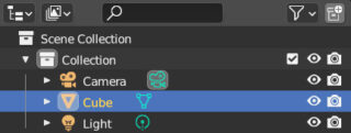
As you can see, there is a hierarchical structure starting from the Scene Collection (always present) containing a different Collection to which the camera, the default cube, and the light belong. This latter collection is the default active one as highlighted by its icon with a light grey background ![]() . By inserting any other object into the scene, it will be part of the active collection. Disabling the eye icon on the right of the collection will make all its elements disappear from the viewport (but they will still be rendered and participate in any physical and not animation). On the other hand, by unchecking the icon located to the right of the collection’s name, it will be completely excluded from the scene. Therefore, we can understand collections as a way to divide and organize our work into different levels. By clicking on the icon
. By inserting any other object into the scene, it will be part of the active collection. Disabling the eye icon on the right of the collection will make all its elements disappear from the viewport (but they will still be rendered and participate in any physical and not animation). On the other hand, by unchecking the icon located to the right of the collection’s name, it will be completely excluded from the scene. Therefore, we can understand collections as a way to divide and organize our work into different levels. By clicking on the icon ![]() on the right in the outliner’s header, we will create a new collection
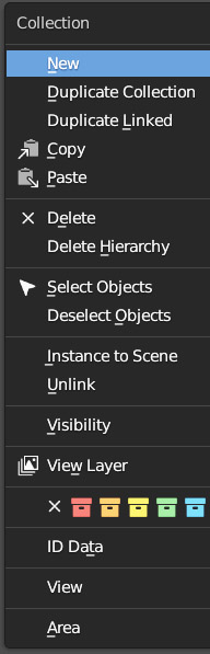
on the right in the outliner’s header, we will create a new collection ![]() which will belong to the Scene Collection unless a different collection (highlighted in the outliner in blue) is selected at the time of its creation. To rename collections, just double-click with the left mouse button on their name so that you can insert the new one. By right-clicking on the names of the collections present in the outliner, the menu on the right will appear with different possible operations, including assigning a color to the various collections.
which will belong to the Scene Collection unless a different collection (highlighted in the outliner in blue) is selected at the time of its creation. To rename collections, just double-click with the left mouse button on their name so that you can insert the new one. By right-clicking on the names of the collections present in the outliner, the menu on the right will appear with different possible operations, including assigning a color to the various collections.
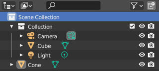
We are free to insert an element into the Scene Collection so that it is the only collection to which it belongs.
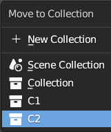
To move an element from one collection to another, we simply have to select it and press the M button, then choose the destination collection from the menu that appears on the screen, or create a new one by clicking New Collection.
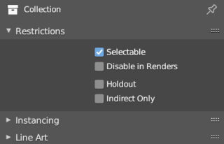
Collections can be nested inside one another simply by dragging them directly in the outliner. Collections have a properties context marked with the icon ![]()
Parenting is another important relationship that can be established between N objects in the scene, according to the hierarchy: parent > child. Whatever the selection of objects, there will always be one of them (the active element) highlighted by an amber border, differently from the orange border of the remaining selected elements

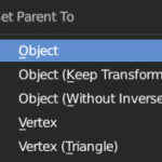
By pressing Ctrl-P and selecting the Object option in the small window that will appear on the screen, all objects will be parented as children of the active element, which will then become the parent.
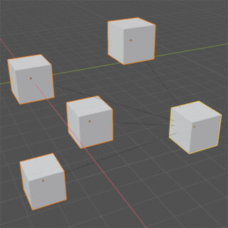
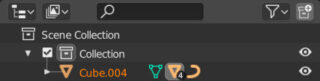
In the 3D View, all children are connected to the parent by a dotted line. In the outliner, only the parent will be visible, with the indication on the right side of the presence of children through different amber-colored symbols depending on their nature. In the following image, we can see the outliner indicating five children: four meshes and one curve.
- By duplicating a child object, the new one will maintain the same parentage with the parent.
- Any other object can be parented with the same procedure: that is, by first clicking the element that will become the child, then the parent, and finally pressing Ctrl-P.
- A child object can in turn be the parent of other N elements and so on.
The fundamental feature of the relationship between parented objects is that the transformations applied to the parent will be transmitted to all the children and the children of the children, that is, to all the elements that belong to the hierarchy parent>child. The parentage can be removed by first selecting the object and then pressing Alt-P.
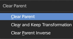
So we can choose to either simply delete the parenting and any inherited transformations, or to remove only the parenting while keeping the transformations.
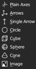
In animations, it is often useful to parent multiple elements to a parent Empty (empty) object, as it is not renderable or editable. By default, the empty object (Menu: Add > Empty) is of the Plain Axes type, which defines a position and orientation in 3D space. You can also choose one of the different shapes visible in the menu to the right, in the context properties ![]()
Other possible relationships between objects are the so-called Constraints, which we will examine in more detail in the chapter dedicated to animation.
Let’s return to analyze the outliner for a moment. The mode in which we have so far used this essential window of Blender is the View Layer (default setting) which mainly concerns showing collections and their elements. By clicking on the icon in the header ![]() we can see the remaining modes.
we can see the remaining modes.
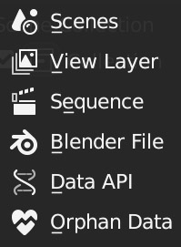
Those that might prove particularly useful when working on more complex projects are: Scenes and Orphan Data. The first shows the different scenes that we will create for a single project, each of which might have multiple View Layers (we will explore the important concept of World in the third chapter).
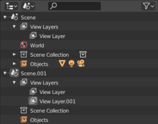
I remind you that the selectors useful for creating new Scenes and View Layers are located on the right side of the fixed menu at the top of the Blender interface. In Orphan Data mode, on the other hand, we will find all isolated objects that do not belong to any collections (not even to the Scene Collection). This is possible because in the Object > Collection menu of the 3D View (in object mode) by choosing Remove From Collection or Remove From All Collections, we can make sure that an object does not appear in any collection, effectively disappearing from the Outliner in View Layer mode.
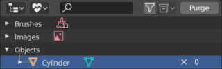
You can restore an orphaned object by dragging it from Orphan Data mode to the 3D View or another outliner window in View Layer mode. Over time, you will notice that many data related to objects that you no longer care about or that you have deleted will accumulate in orphan data. In that case, you can clean up the orphan data list by clicking on the Purge button in the outliner header one or more times.
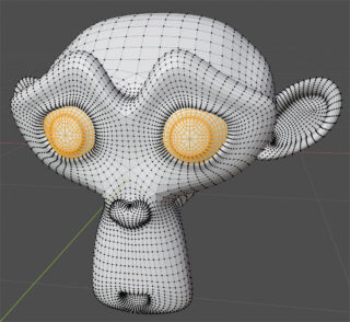
When it will be necessary to apply a set of effects or modifiers to individual parts of a mesh, or when you will need to store a selection of vertices to be called up promptly later, the Vertex Group comes in handy. Take the Suzanne mesh divided with the SubSurf modifier, and suppose we want to group the vertices of one of its parts, for example the eyes.
Once we’ve made our selection (obviously in edit mode), we click on the icon ![]() to access the Object Data context
to access the Object Data context
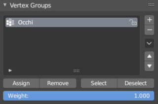
Here in the Vertex Groups panel, click on the + symbol to add a new group (to change the name of the Vertex Group, just double-click on it). Then, with the vertices still selected, click on Assign to assign the selected vertices to the created group. From now on, you can deselect (deselect button) and reselect (select button) the group at your convenience.
Next paragraph
Previous paragraph
Back to Index
Wishing you an enjoyable and productive study with Blender, I would like to remind you that you can support this project in two ways: by making a small donation through PayPal or by purchasing the professionally formatted and optimized for tablet viewing PDF version on Lulu.com