Experimenting with subdivision, extrusion, and editing functions (among other tools that we will examine later) we can end up with models with a lot of vertices and faces. Any modern PC can easily handle meshes made up of millions of polygons, both in the modeling phase and in the final rendering. However, if we wanted to assign a Soft Body physics to these models for animation (think of a slightly deflated ball, for example), the work for the CPU could become quite heavy. There is no mathematical rule that can determine the number of polygons that are suitable for creating a 3D model. It is more a matter of finding a good balance based on the desired result, remembering that the level of detail depends not only on the polygonal complexity of the models, but also and above all on the shading, that is, on the behavior of Materials exposed to light sources. Blender provides us with a fast OpenGL graphics engine called Workbench, which is particularly useful in the modeling phase. We access the Render context of the properties by clicking the icon ![]() here, in the Render panel we set the engine
here, in the Render panel we set the engine ![]() . Then, in the header of the 3D View on the right, we select the Rendered shading type by clicking the icon
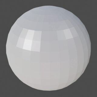
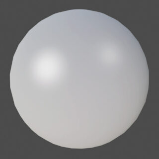
. Then, in the header of the 3D View on the right, we select the Rendered shading type by clicking the icon ![]() . Now we insert the UV Sphere primitive into the scene and enable Shade Smooth for it from the Object Context Menu of the 3D View (in object mode). You will immediately see that this shading largely succeeds in hiding the low number of polygons. In edit mode, we can set the shade smooth/flat only for a selection of faces from the Face Context Menu. While from the Mesh > Shading menu (still in edit mode) we will access options related to shading of edges and vertices.
. Now we insert the UV Sphere primitive into the scene and enable Shade Smooth for it from the Object Context Menu of the 3D View (in object mode). You will immediately see that this shading largely succeeds in hiding the low number of polygons. In edit mode, we can set the shade smooth/flat only for a selection of faces from the Face Context Menu. While from the Mesh > Shading menu (still in edit mode) we will access options related to shading of edges and vertices.
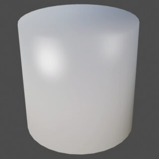
If the curved surface of the model is bounded by flat surfaces, as is the case with the circular edges of the cylinder, smooth shading will try to round off the top and bottom edge as well, resulting in an unpleasing appearance.
To see the cylinder perfectly rounded only on the curved surface, we must apply Shade Auto Smooth from the Object Context Menu. Once this is done, go to the Object Data context, icon ![]() where in the Normals panel we will find Auto Smooth enabled.
where in the Normals panel we will find Auto Smooth enabled.
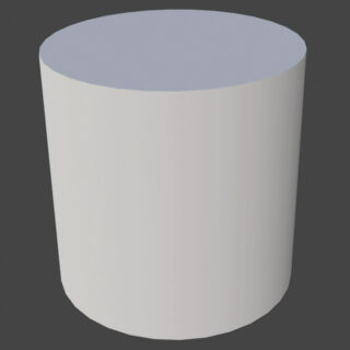
The default value of 30° is the maximum angle between the normals of adjacent faces beyond which the shader will not soften the surface (in the case of a cylinder with circular edges of 32 vertices, a value of 12° will suffice; therefore half for a cylinder with 64 vertices).
OpenGL / Workbench smooth shading is only an approximation of the more complex algorithms that we will find in Eevee and Cycles; however, it allows us to reveal any problems already during modeling. In fact, good smoothing of curved surfaces should be sought from the initial stages of model design, which may be obtained by the union of two or more parts modeled individually. If different curved meshes are joined together to form a more complex (still curved and without corners) surface, a good final smoothing will require exact correspondence of the vertices between the different parts. For example, take a simple UV Sphere of which one half has a higher polygonal detail than the other. Applying smooth shading will show a clear separation line that is particularly evident in the directly illuminated and shadow areas. It sometimes happens that the imperfection of the smoothing is not easily perceptible during modeling, but unfortunately very obvious in the render.
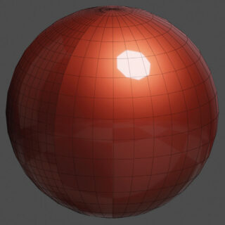

The advice is first of all to identify such problems by observing the model in the 3D View in one of the MatCap modes available for the Workbench engine that you can activate from the lighting panel.
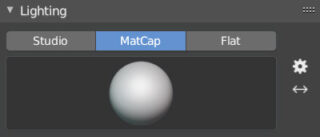
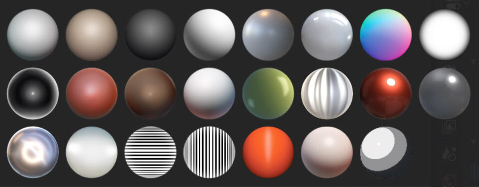
By clicking the preview image, you can access the various options for shading the model in the 3D view.
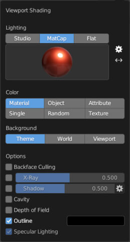
MatCap is also available for Solid view when using the Eevee and Cycles engines, just click on the arrow icon to activate the next menu: ![]()
During the modeling process, it may happen that different faces of the same mesh are partially overlapped; in this situation, the 3D view will return artifacts such as the one visible in the top image called “Z-Fighting”, that is a condition in which the graphics engine is unable to determine the rendering order of the different surfaces based on depth. A result to be avoided and which can be remedied by modifying the mesh if necessary.
Next paragraph
Previous paragraph
Back to Index
Wishing you an enjoyable and productive study with Blender, I would like to remind you that you can support this project in two ways: by making a small donation through PayPal or by purchasing the professionally formatted and optimized for tablet viewing PDF version on Lulu.com