In edit mode, select a vertex of the default cube and start the extrude with the press of the E key. You will get a new vertex (extruded) plus an edge connecting this with the original vertex. Extrusion operations must always be completed with a left mouse click.
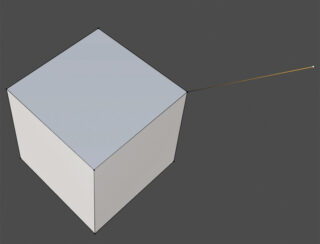
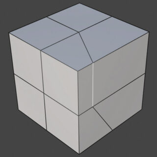
Select the edge just obtained and repeat the same extrusion operation on it. This time you will get a rectangular face as the one shown in the figure.
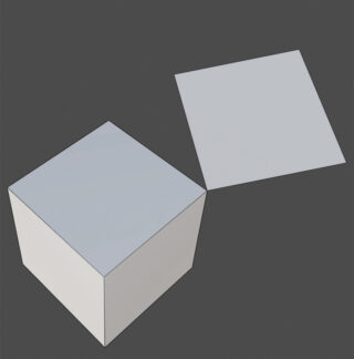
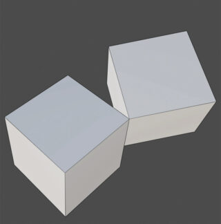
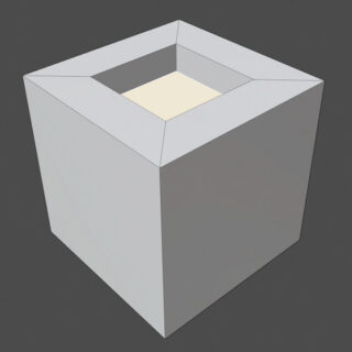
By extruding the face, we will see the formation of an entire solid. With three extrusions, we went from the zero dimensions of the starting vertex to the three-dimensionality of a volume.
When extruding any face, you will notice that, unlike vertices and edges, the movement of the extruded element in this case occurs along the direction orthogonal to the original face.
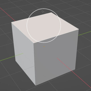
So let’s start again from the default cube and, in edit mode, select one of its faces; then click the icon

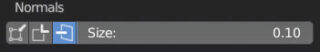
in the toolbar to start the Inset Face tool. Just click with the left button inside the circle, hold down the pressure and move the mouse, to create a face inside the starting one and identical to it:
then we select and extrude the new face (E key) being able to perform either an external extrusion or an internal one, as the movement of the extruded face is constrained to the two orthogonal directions to the surface, as mentioned before.
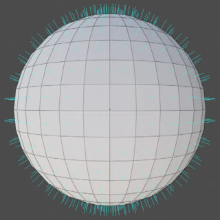
In fact, each face of the model has its own Normal, with an orientation along the axis orthogonal to the surface itself. In closed solid figures, such as a sphere, all normals must be directed outward. To better understand the concept, we insert the UV Sphere primitive in the scene and go into edit mode, then open the Viewport Overlays menu (where you can disable or enable the visibility of the various elements of the viewport) by clicking the arrow next to the default active Show Overlays icon ![]() in the rich menu that appears on the screen, we will find the Normals panel at the bottom, which allows you to activate the visibility of the normals.
in the rich menu that appears on the screen, we will find the Normals panel at the bottom, which allows you to activate the visibility of the normals.
Here we find three icons: with the first one, we will see the normals appear on the vertices, the second shows groups of normals that originate on each vertex (whose vector mean, or interpolation, is the normal seen before), the third and most interesting option shows the normals on the individual faces.
In edit mode, you can reverse the orientation of a normal simply by selecting the face of interest and selecting Flip in the Mesh>Normal menu. For any of the transformations covered in the first chapter, it might be useful to have an orientation fixed on the normal of the selected element, such as when we want to translate a face of the model just along that direction.
So far we have extruded by simply pressing the E key. In the toolbar we find an icon dedicated to this too

As you can see, the icon has a small triangle in the lower right corner that indicates the presence of different modes, which will appear with a prolonged press of the left mouse button.
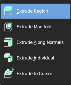
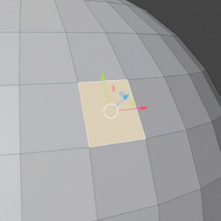
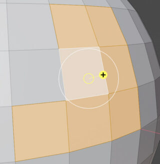
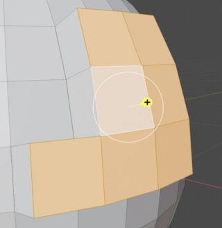
Try extruding a portion of the surface of a curved model (UV Sphere) with the Extrude Region mode. You will immediately notice the appearance of the yellow manipulator with a + sign in the circle: by acting on it, you will see that the extrusion takes place uniformly along the “average” normal of all the individual normals of the selected faces.
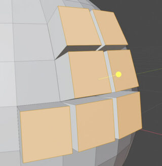
You will see a compact raising (or lowering) of your selection of faces. On the other hand, if you select Extrude Individual, you will get each individual face to be extruded along its own normal:
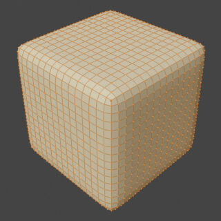
In edit mode, with all the faces of a mesh selected, we can perform other interesting operations directly accessible from the toolbar. Let’s start with the default cube divided several times, and after selecting Smooth Vertices through the icon

click on the yellow vector while moving the mouse in any direction. This will display the tool panel
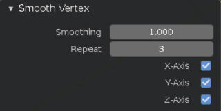
that will tend to soften the sharp areas without changing the total number of faces. You can increase the effect with a greater number of Repeats.
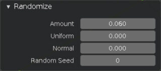
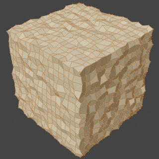
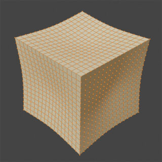
Randomize (together with smooth vertex in the toolbar) icon

varies randomly the positions of all selected vertices according to the parameters visible in the image
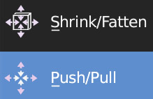
Push/Pull, the secondary icon of Shrink/Fatten, makes a model, finely detailed, of cubic type (that is, with edges) convex or concave.
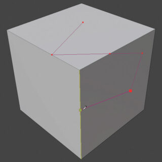
The functioning of Knife. icon

is intuitive and it will take a few tries to learn it. Without selecting any face, with the mouse we will move a cursor that will remain “attached” to the surfaces allowing the easy addition of new vertices with a simple left click. To make cuts inside any surface (even a single quad face) you must create a closed broken line on it. The operation must finally be completed and confirmed with the space bar. The cursor will automatically also attach to the edges of the mesh very accurately, so we can create a new face through two or more vertices.
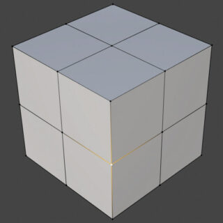
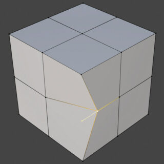
During the modeling phase, the two simple functions Vertex Slide and Edge Slide may be important
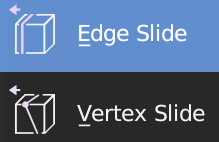
respectively useful to slide a vertex along the edges it belongs to and similarly the edges on the surfaces
Now that we know that thanks to extrusion it is possible to start modeling from:
- a single vertex
- a plane
- a cube
- from a curve (paragraph 2.4)
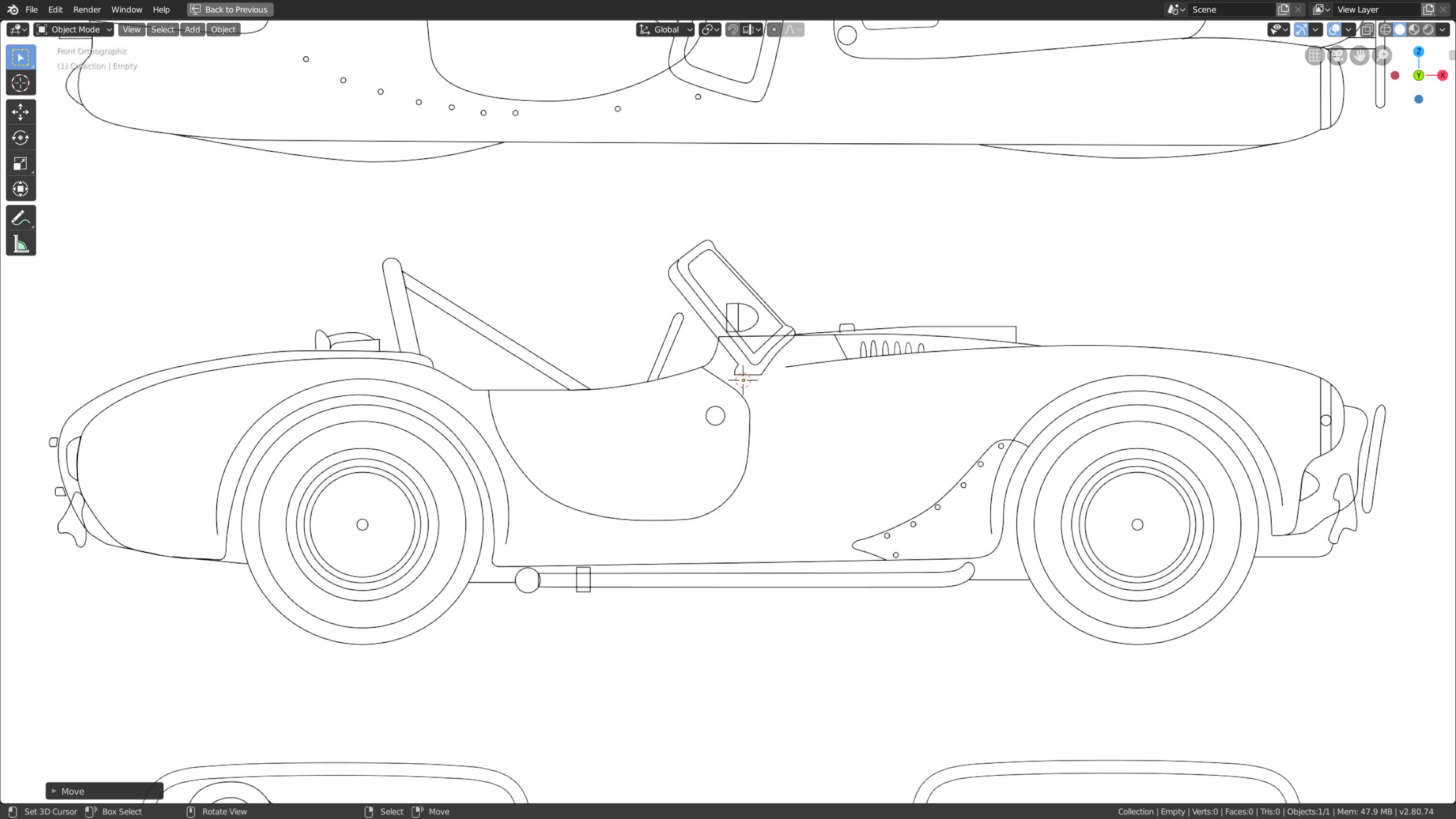
we can use images related to the model we want to recreate by applying them as a background in the 3D View. This technique, also known as point to point (the equivalent of tracing in drawing), will be quite simple and immediate for all those objects that can be approximated by a flat figure “extruded” along a direction (a bit like cylindrical surfaces come out by extruding simple circles). Once the extrusion of the flat surface has been made, made “on top” of the background image, the profile of the mesh will be clearly rectangular (even a cylinder will appear rectangular laterally) at that point with the tools so far illustrated it will be possible to divide and modify the silhouette in this perspective to make it coincide with a second image of the object applied as a background in the respective projection. Having a blue print of the object (many free collections can be found on the net) that is, images of the three orthogonal projections, we can patiently reconstruct every detail of it and obtain very satisfactory results. One common use of this technique, shown in many video tutorials available online, is to model the entire body of an automobile with good results in a relatively short time. It all depends on the characteristics of the model we want to reproduce, whether it is symmetrical with respect to a plane, whether it has many curved or squared parts, etc. In 3D modeling there is not a single way to achieve the desired result and only with accumulated experience will it be intuited from the beginning how to proceed, maybe with a bit of healthy trial and error. To insert a background image, first place yourself in one of the orthographic views, for example front (press 1 on the numeric keypad), then from the Add>Image menu in the 3D View, choose ![]() . At this point, using Blender’s usual file manager, we will select the image from our hard disk, which will immediately appear in the ortho view.
. At this point, using Blender’s usual file manager, we will select the image from our hard disk, which will immediately appear in the ortho view.
Just bring the mouse pointer to the edges of the image and they will be immediately highlighted by a yellow outline, at which point you can change the size of the image.
By bringing the pointer to the center of the image you can move it to your liking. Other options can be found in the Object Data properties context ![]() .
.
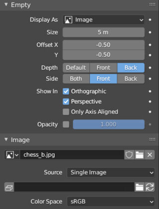
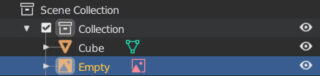
In fact, the background image is an object in the scene (also visible in the outliner) of type Empty that can also be displayed in perspective mode (checking the Display Perspective box) and always appear ‘behind’ any mesh (Depth = Back). By inserting the Background image directly from the perspective view, it will automatically be oriented in the direction of the camera.
Next paragraph
Previous paragraph
Back to Index
Wishing you an enjoyable and productive study with Blender, I would like to remind you that you can support this project in two ways: by making a small donation through PayPal or by purchasing the professionally formatted and optimized for tablet viewing PDF version on Lulu.com