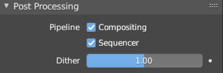
In the Post Processing panel of the Output context, icon ![]() the Compositing box is active by default:
the Compositing box is active by default:
The ways of using the Compositor are almost infinite, which is why we will only expose some basic principles aimed at modifying the final rendering of our renders.
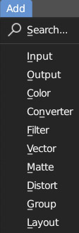
The nodes available to us are divided into ten categories: Input, Output, Layout, Group, plus six important subcategories of Processing nodes, and we can insert them into compositing from the Add menu (Shift-A) which also includes the convenient Search option to type the name of the searched node.
Input Nodes
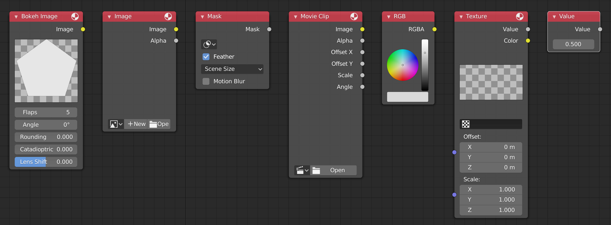
Nodes useful for introducing external elements to the 3D scene context into the compositing, to be used both for their yellow output socket, of the color type, and for the gray sockets if these elements contain the alpha channel or other useful numerical data.
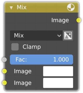
Color – Mix Nodes
This node already seen in the previous paragraph, mixes two images using one of the usual 18 blending techniques.
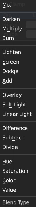
By default we find Mix active, that is, the linear interpolation between two images. The image connected to the yellow socket at the top acts as a background, while the other image connected to the socket below is the one that in the node will be superimposed on the background. Fac varies from zero (only background) to 1 (only overlapping image) and is controlled by a gray socket; therefore, the blending value could be associated with an Alpha or Z parameter, variable pixel by pixel, rather than uniform and equal to the manually entered Fac number; that is, the typical case of applying an intensity map. (In Fac it is possible to enter values greater than those normalized (<= 1) and as large as desired).
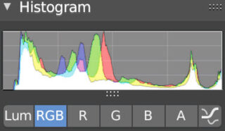
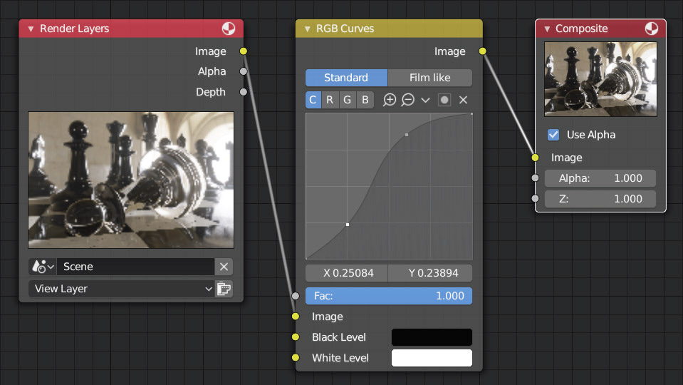
RGB Curves:
With this node, we can perform a refined adjustment of the color, brightness (C channel) or on each individual R G B channel, through curves that can be modified at will in a very intuitive way, with a number of control points as desired. For this purpose, the histogram visible in the Image Editor window (view mode), Scopes tab of the sidebar (N key) may be very useful.
Bright/Contrast:
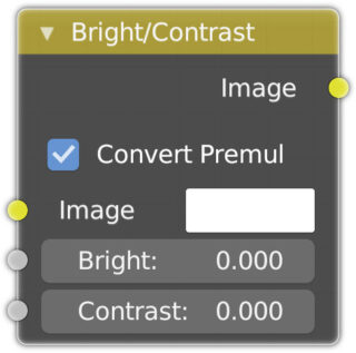
Node to adjust brightness and contrast.
Set Alpha (Converter family):
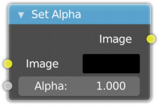
Assign the Alpha channel to any image lacking it. With this node, we can, for example, decide which parts of the image should be transparent using, for example, a mask.
Filter: Blur
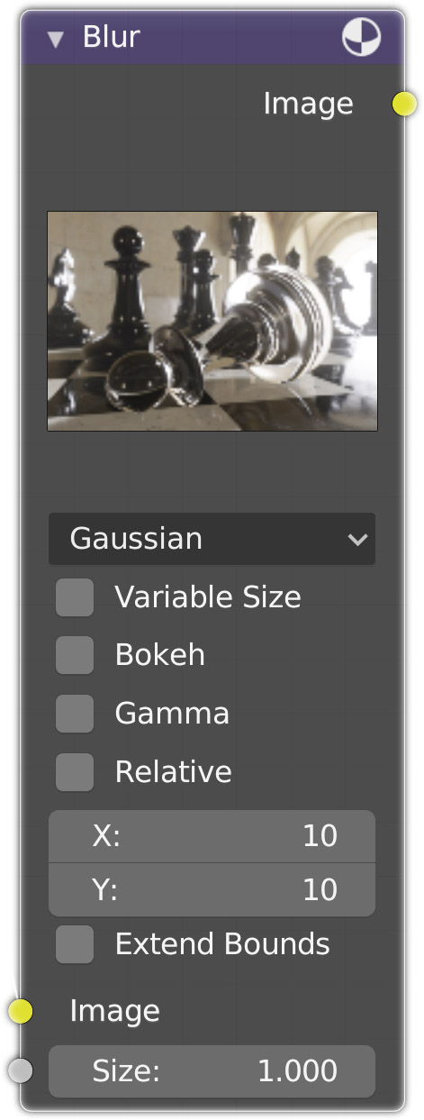
Node for a uniform Gaussian blur (other algorithms are also present), or non-uniform and socket-guided Size
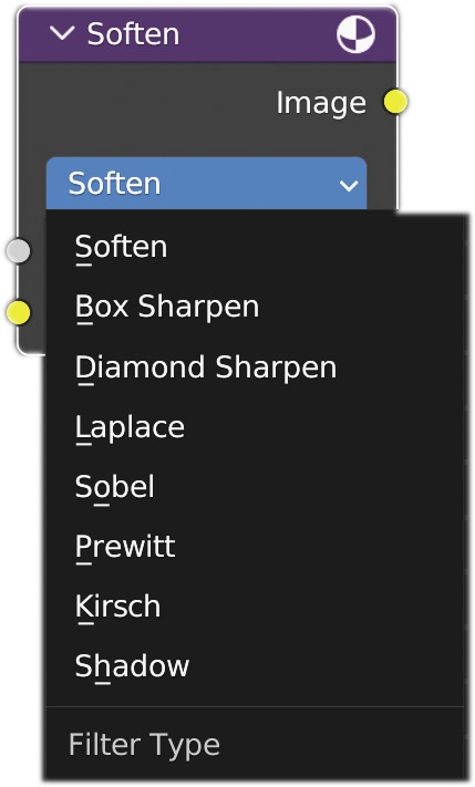
Filter:
Allows the application of one of several filters, gradually, varying Fac from 0 (none) to 1 (maximum):
- Soften is a slight blur.
- Box Sharpen enhances edges.
- Diamond Sharpen is less aggressive than the previous one.
- Laplace softens edges.
- Sobel, Prewitt, and Kirsch highlight edges by using a negative of the image.
- Shadow creates a relief effect around the edges.
Distort Nodes:
Scale
Translate
Rotate
Transform
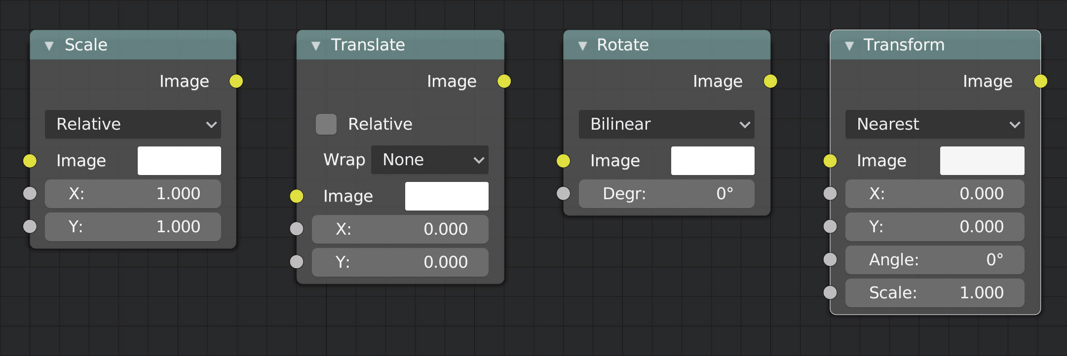
Series of nodes for separate scaling, x and y position, or rotation transformations; plus the Transform node to perform all the previous ones together.
Lens Distorsion:
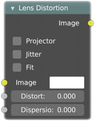
Simulates some of the optical distortions of cameras. The main parameter is Distort, which can take positive values to create a central bulging of the image, or negative values for a central shrinkage..

Dispersion instead recreates chromatic aberration, a defect due to the passage of different components of light (at different wavelengths) through the lens optics which will not all have the same refraction index. The jitter box, if activated, speeds up the process with the presence of optical noise. Fit fits the distorted image (positive values) to avoid the formation of transparent areas in the images. Projector, if active, disables Jitter and Fit.

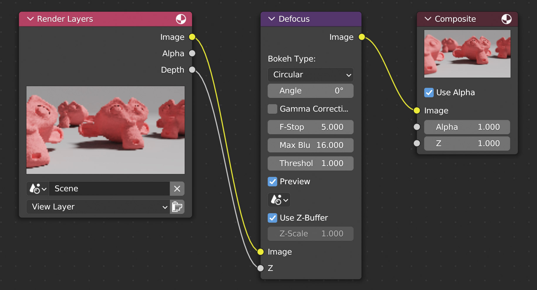
Other Filter Nodes: Defocus
The Defocus node is typically used to create depth of field, in which case we will finally see the use of the Z coordinate (Depth) during compositing. We already know that DOF is natively simulated by the Eevee and Cycles engines where we can choose to focus on a single object, or to focus on what is located at a certain distance, blurring the rest. The advantage of creating this effect in post-production is the ability to change the focus without having to render the scene again. The main parameter of the node is again F-Stop (par. 3.10) with which to narrow or widen the focus. In the object data context of the camera, in the Depth of Field panel (which you can leave disabled) you must indicate the object to focus on (its origin will be considered) or the distance. The interesting thing is that this choice can be changed after the rendering is completed (in this case it will be necessary to update the compositing, for example by reinserting the same value into any parameter of the node).

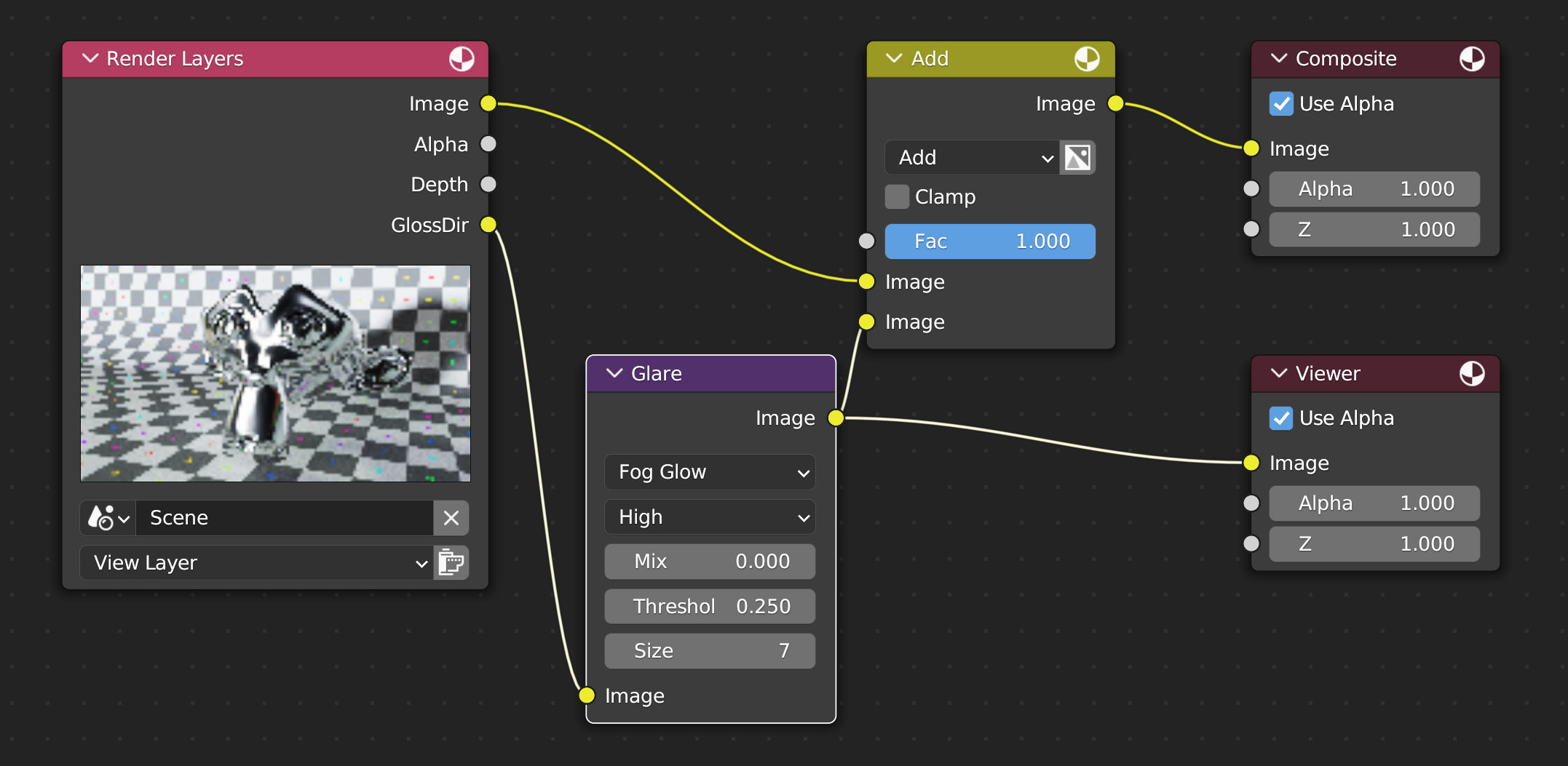
Glare
Node for creating various types of glare useful for clarifying what was said at the beginning of the paragraph, that is, how it is possible to retouch the rendering, intervening in its intimate mechanisms, in order to easily obtain particular effects. Let’s try to apply the Glare Node to the reflections of the past ![]() (Cycles engine). Simply mix (add) the full rendering with the image obtained by applying Glare to only the Specular pass enabled in the Render Layers (the result can be seen in the Viewer node). Four types of glare with three levels of quality are available. The final effect will depend a lot on the brightness of the scene.
(Cycles engine). Simply mix (add) the full rendering with the image obtained by applying Glare to only the Specular pass enabled in the Render Layers (the result can be seen in the Viewer node). Four types of glare with three levels of quality are available. The final effect will depend a lot on the brightness of the scene.

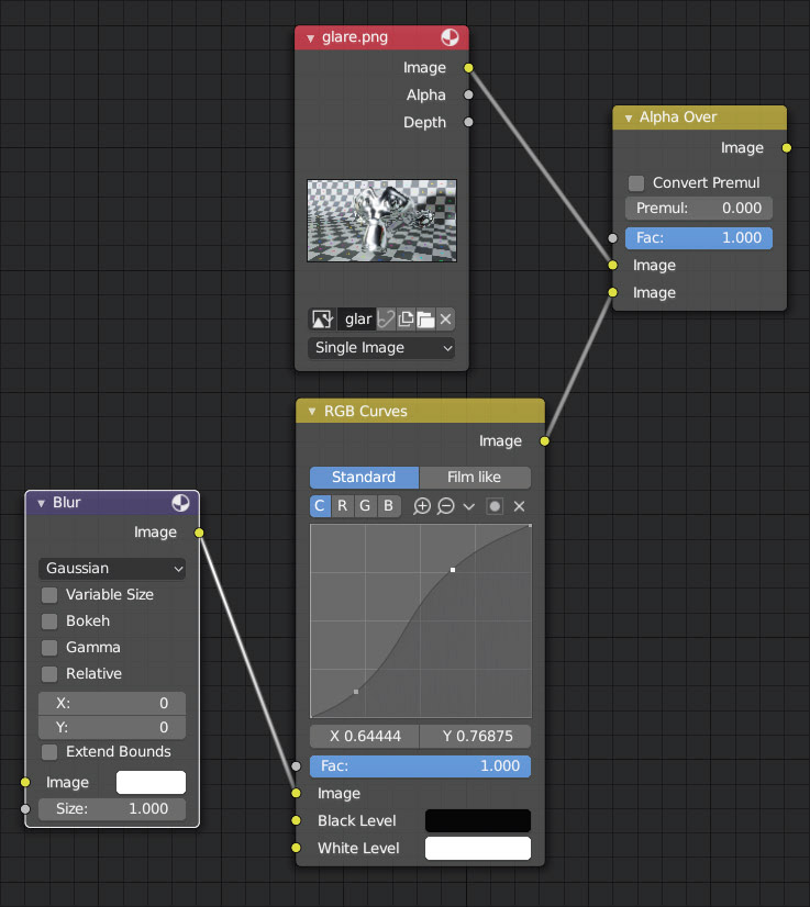
Therefore, it is possible to create very complex compositing using the node editor, possibly with the need to repeat operations several times by concatenating different nodes. To give order to the layout, we can group all the nodes we want, obviously according to the logic of our compositing. Observing the nodes in the following image, we see that their overall action takes place through six input sockets and only three output sockets (we are talking about the sockets that do not have a thread connected).
To group a set of interconnected nodes, we will first have to select them and then press Ctrl-G (or go to Node>Make Group in the header of the compositor) to enter edit mode, where the highlighted nodes will have a new Group Input on the left and Group Output on the right (only visible during the group definition phase).
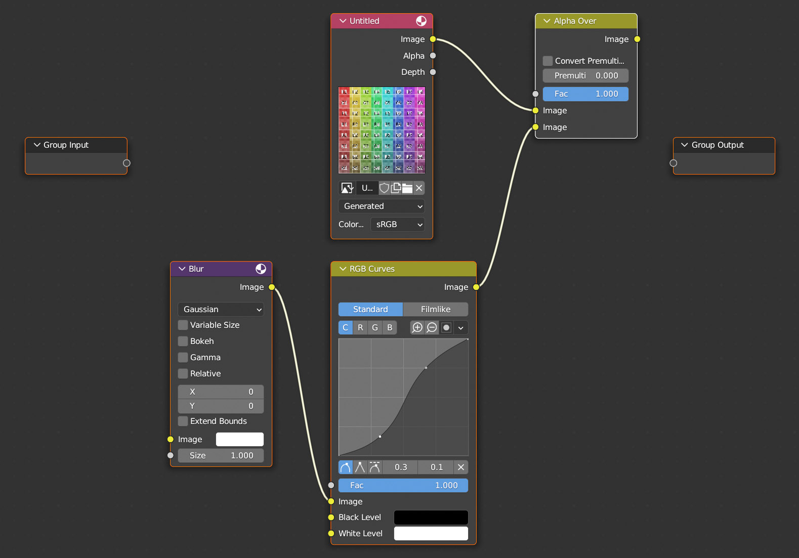
Let’s start with Group Input, which as we can see has only one free socket on the right to connect to one of the input sockets of our nodes, for example the image socket of the Blur node (first in the logical structure of the nodes).

The initially empty socket has now become yellow with the text “image” next to it, while a new empty socket has appeared below to be connected to another input socket of our node group. The operation must then be repeated until all the sockets of interest are involved, and then the same must be done with the Group Output node and the output sockets. The group definition is completed and started by pressing the Tab key. In the compositor sidebar (press N)> Node tab> Node field, you can assign a label to the group of nodes. To dissolve a group, just select the corresponding node and press Control-Alt-G.
To order the layout, we will also have the Frame node (Layout family) available.
After inserting the Frame node in the node editor, any node that is moved inside it will be captured by the overall frame.
- Moving the Frame along the node editor window will cause the nodes inside to move coherently with it.
- Moving a single node belonging to the frame will automatically resize the frame.
- Finally, you can give a textual description to the frame in the Node> Label field in the Nose tab of the sidebar.
A node can be released from the frame and returned outside with Alt-P.
Next paragraph
Previous paragraph
Back to Index
Wishing you an enjoyable and productive study with Blender, I would like to remind you that you can support this project in two ways: by making a small donation through PayPal or by purchasing the professionally formatted and optimized for tablet viewing PDF version on Lulu.com