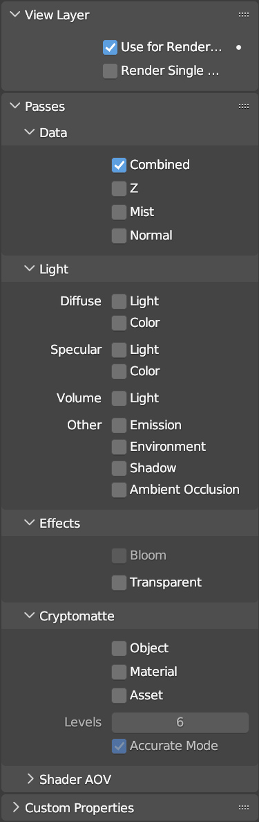
The rendering process (F12 button) always ends with the combination (compositing) of certain intermediate steps called Passes. Blender allows you to use individual passes (usually invisible) in order to process the compositing phase according to your needs. The list of passes related to the engine in use can be found in the View Layer context of the properties, icon ![]() , here is how it appears in Eevee:
, here is how it appears in Eevee:
and then in Cycles
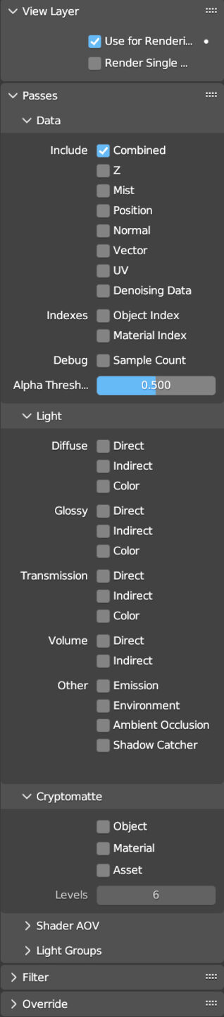
As you can see, it has a larger set of passes. Now let’s look at Blender’s Compositing workspace (at the top of the page next to it). The main window of this layout is the ![]() which uses a node system almost identical to the shader editor, provided that you check
which uses a node system almost identical to the shader editor, provided that you check ![]() at the top left in the header. This will immediately show the Render Layers and Composite nodes. Although these nodes are different from those used in the shading phase, their operation is entirely analogous to the yellow (color data), grey (numeric data), and purple (vector data) color sockets.
at the top left in the header. This will immediately show the Render Layers and Composite nodes. Although these nodes are different from those used in the shading phase, their operation is entirely analogous to the yellow (color data), grey (numeric data), and purple (vector data) color sockets.
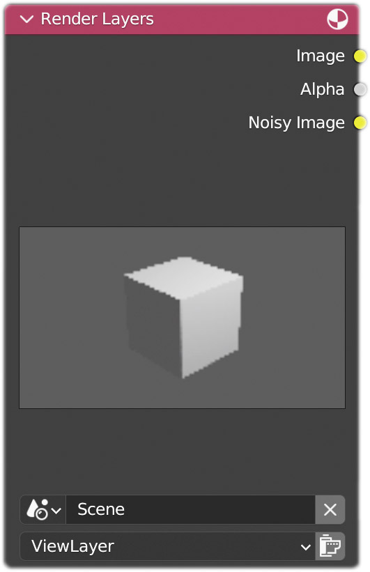
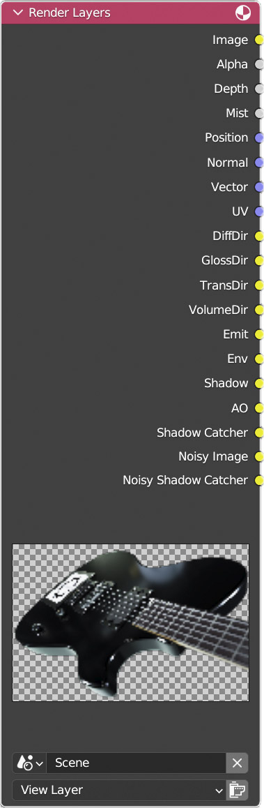
On the Render Layers node (input family), we will find three output sockets:
- A yellow socket called Image the render) connected to the composite node of the same name.
- A grey socket called Alpha (the potential transparency of the render)
- A yellow socket called Noisy Image
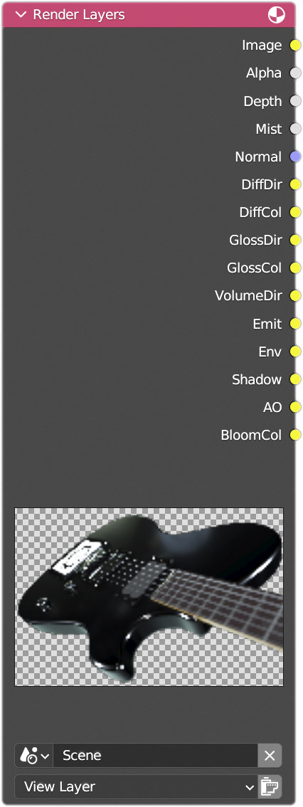
The Image and Alpha nodes are always present, while Noisy Image is simply the image without denoising (if enabled). Below you can see the comparison between the eevee (left) and cycles (right) render layers nodes with the main passes enabled. At the moment these passes may appear mysterious to you: you know they exist, but you have no idea how to use them or how to observe them.
Let’s insert the View node (output) which allows us to directly see the individual passes within the same compositor window. Let’s arrange the nodes as shown in the image below (this works with any scene: eevee or cycles). After activating the Ambient Occlusion (AO) and Mist passes.
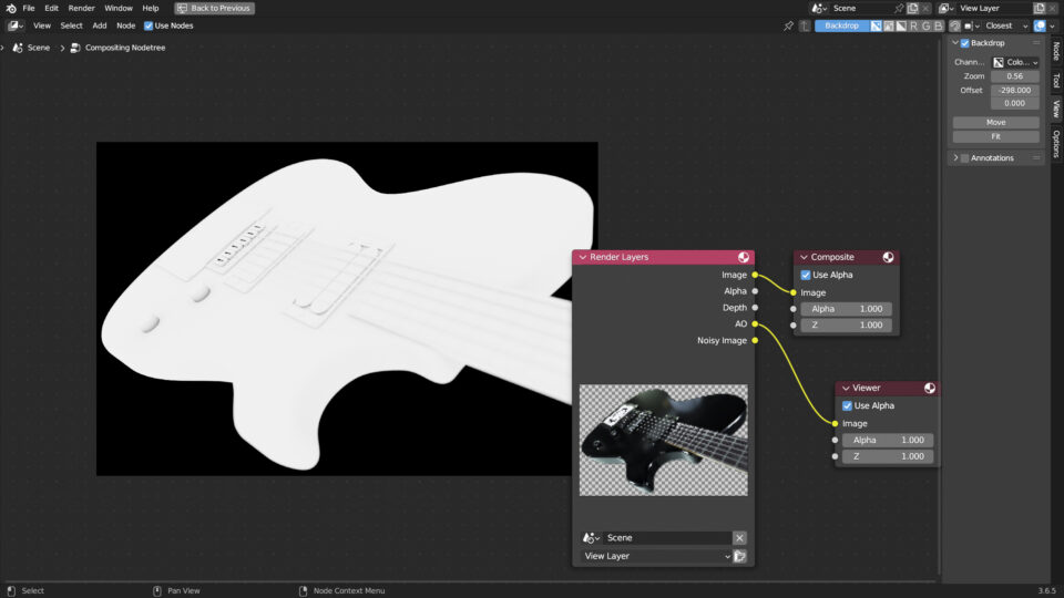
start the rendering, making sure that the Backdrop ![]() is active, in this way we will see the pass as a background image and we can also choose between the full display of the image (color + alpha) or other partial displays: color, alpha channel, R, G and B color components. Subsequently, in the usual sidebar (N button), View tab, we can set the zoom level and the position of the background image with the Backdrop panel settings. With the Fit button, the image will automatically fit the vertical size of the window. The background image will also be available in the Blender Image Editor window, just choose Viewer Node
is active, in this way we will see the pass as a background image and we can also choose between the full display of the image (color + alpha) or other partial displays: color, alpha channel, R, G and B color components. Subsequently, in the usual sidebar (N button), View tab, we can set the zoom level and the position of the background image with the Backdrop panel settings. With the Fit button, the image will automatically fit the vertical size of the window. The background image will also be available in the Blender Image Editor window, just choose Viewer Node ![]() . If we have multiple Viewer nodes in the compositor, the image of the selected one will be shown. When the Use Alpha box is unselected, any transparent areas of the images will be represented by black pixels.
. If we have multiple Viewer nodes in the compositor, the image of the selected one will be shown. When the Use Alpha box is unselected, any transparent areas of the images will be represented by black pixels.
Passes that have a yellow socket can be directly displayed in Composite and Viewer nodes, but what about those connected to a grey socket? Technically there is nothing stopping us from connecting grey output sockets to yellow sockets, in which case numerical data (if expressed in a normalized range, that is, between 0 and 1, as in the case of Alpha and Z coordinates) is transformed into black and white monochrome images. However, the conversion to 256 shades of grey may be rough because the values expressed by grey sockets are floating point numbers. For example, if the scene were made up of surfaces very close to or very far from the camera, the Z coordinate would have values at the extremes of the range 0 and 1, ending up being interpreted as a completely black or white image. I therefore do not recommend connecting nodes using sockets of different colors because it is possible to act differently. For example, let’s take the Mist pass and create the node system shown in the following image.
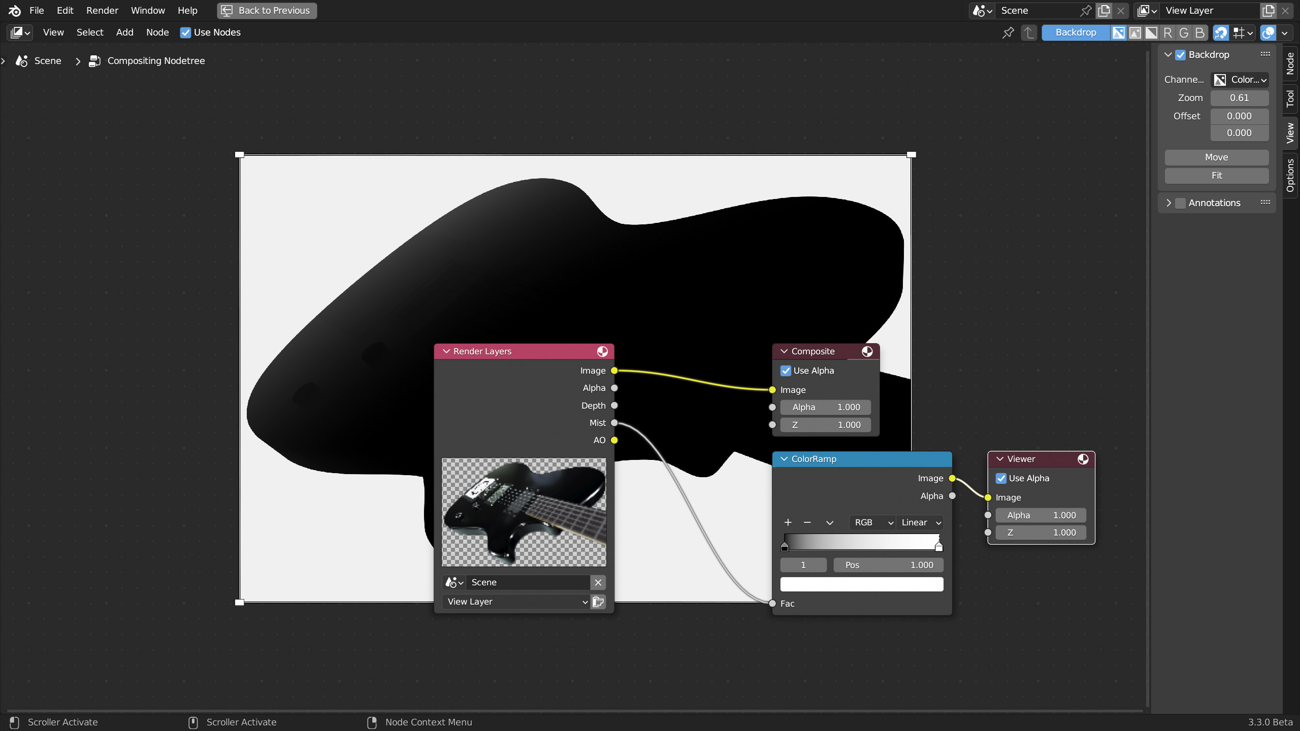
As you can see, I used the ColorRamp node (Converter family) in order to correctly transform the numerical information carried by the grey socket into an image with a yellow output node.
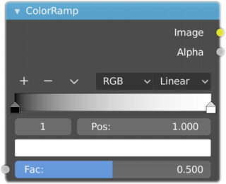
This node is used to define a gradient using any number of colors that are black (indicator on the left) and white (indicator on the right) by default. You can click and move these active colors to your liking in the range, change their hue by clicking on the colored box at the bottom, add or remove other colors. Finally, you can choose the interpolation between: Linear, Ease, Cardinal, B-Spline, Constant. With the default gradient, moving the white selector to the left causes visibility to decrease. The opposite happens when moving the black to the right (the important thing is to avoid reversing the order). At this point we simply need to add the Mix node (Color family) and choose the Add blending mode between the original render and the Mist pass, as in the image below.
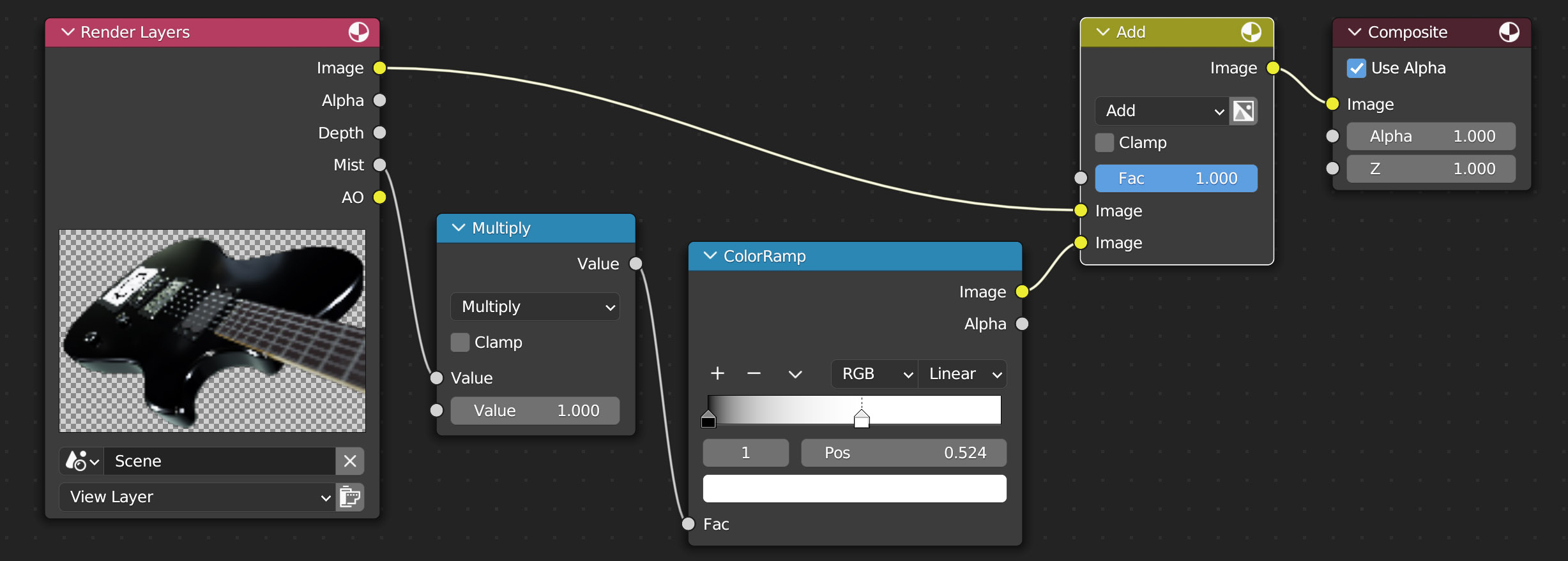
As you can see, I also introduced the Math node (Converter family) with the Multiply operation, in order to increase (value>1) or decrease (value<1) the intensity of the fog to your liking. Remember that for each node variation, compositing is reworked starting from the render.

Next paragraph
Previous paragraph
Back to Index
Wishing you an enjoyable and productive study with Blender, I would like to remind you that you can support this project in two ways: by making a small donation through PayPal or by purchasing the professionally formatted and optimized for tablet viewing PDF version on Lulu.com