In this last part of the chapter, we will discuss some techniques for dynamically transforming meshes whose approach is similar to that of posing jointed mannequins or moving puppets. This means that we will not act directly on the vertices of the meshes, but we will make the vertices adapt to the movements of a kind of skeleton (the armature) consisting of a set of interconnected bones.

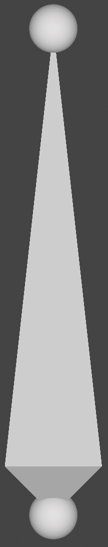
We insert the Armature object into our scene, which by default consists of a single bone represented as a solid of eight triangular faces (octahedron) placed between two spheres, of which the one at the bottom is the root or head of the bone, while the one at the top is the tail of the bone.
Armatures are therefore non-renderable objects that only appear inside the 3D View. In addition to the object/edit mode, armatures have the additional use mode called Pose Mode.
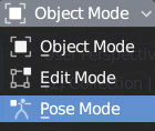
Let’s start with the edit mode where we can select either the entire bone by right-clicking on the octahedron, or one of the two ends. The same transformations seen for normal meshes apply here, and it will take a few minutes of testing to realize that:
- moving the root and tail will increase the overall size of the bone in proportion
- the center of gravity of the bone is at the center of its root
- a selection of bones can be duplicated with Shift-D
- both ends can be extruded to obtain a new bone.
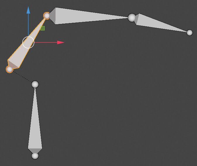
The result of the extrusion depends on whether it concerns the root or the tail. In the first case, the root of the extruded bone will coincide with that of the starting bone and will be disconnected and independent from it.
Extruding the tail, on the other hand, will produce a bone related and connected to the original bone.
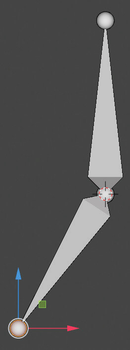
In a chain of two or more bones created in this way (that is, through extrusions), the scale, rotation, and location transformations performed on a single Bone will also involve the adjacent ones.
To verify the relationship between the bones, or to connect them to each other, or to disconnect them and change their name, we must go to the Relation panel in the Bone context, icon ![]() in edit mode.
in edit mode.
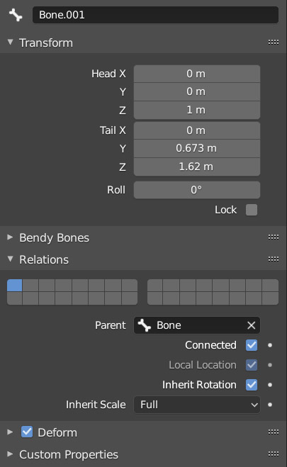
In the Parent field, for example, we see that bone.001 is related and connected to bone from which it originated by extruding the tail, inheriting (inherit) the effects of the scale and rotation transformations (as we will see later in pose mode). We can therefore disconnect the bone by unchecking Connected and maintain or not the relationship (a dotted line will appear). At the moment we ignore the other panels.
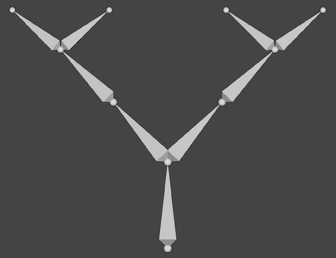
In addition to linear chains of bones, it is obviously possible to create branching or mixed ones.
The structure we will create in edit mode is nothing more than the rest position (Rest Position) of the armature. This position must be created (as we will see in the next paragraph) “inside” the model, assuming that it is also in its rest position. Subsequently, in Pose Mode, we can change the position of the bones, creating all the poses we need, but we cannot modify the rest position from here.

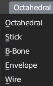
In the Viewport Display panel of the Object Data context for the armature (available in Object, Edit, and Pose Mode), icon ![]() we find five different types of representation of armatures.
we find five different types of representation of armatures.
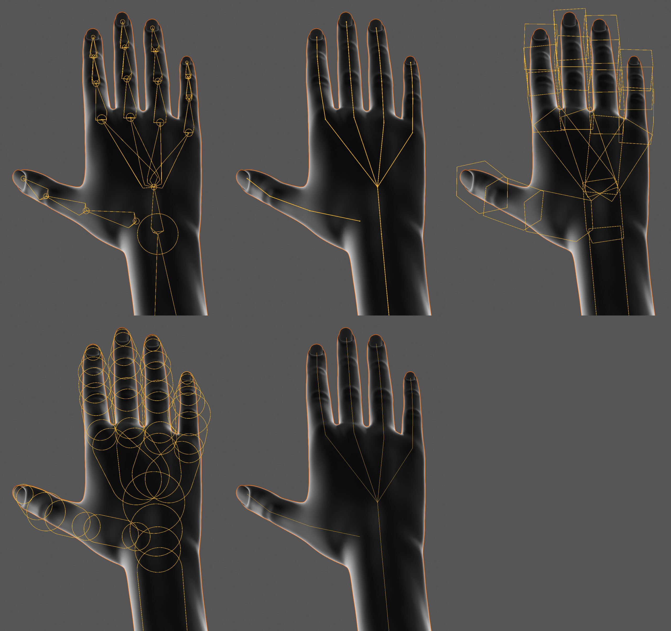
In edit mode, the envelope mode reveals the existence of a 3D aura of grey color that surrounds the bone: it represents the area of influence of the single bone on the vertices of the mesh in the process called Skinning.
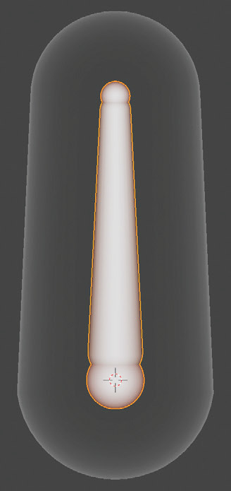
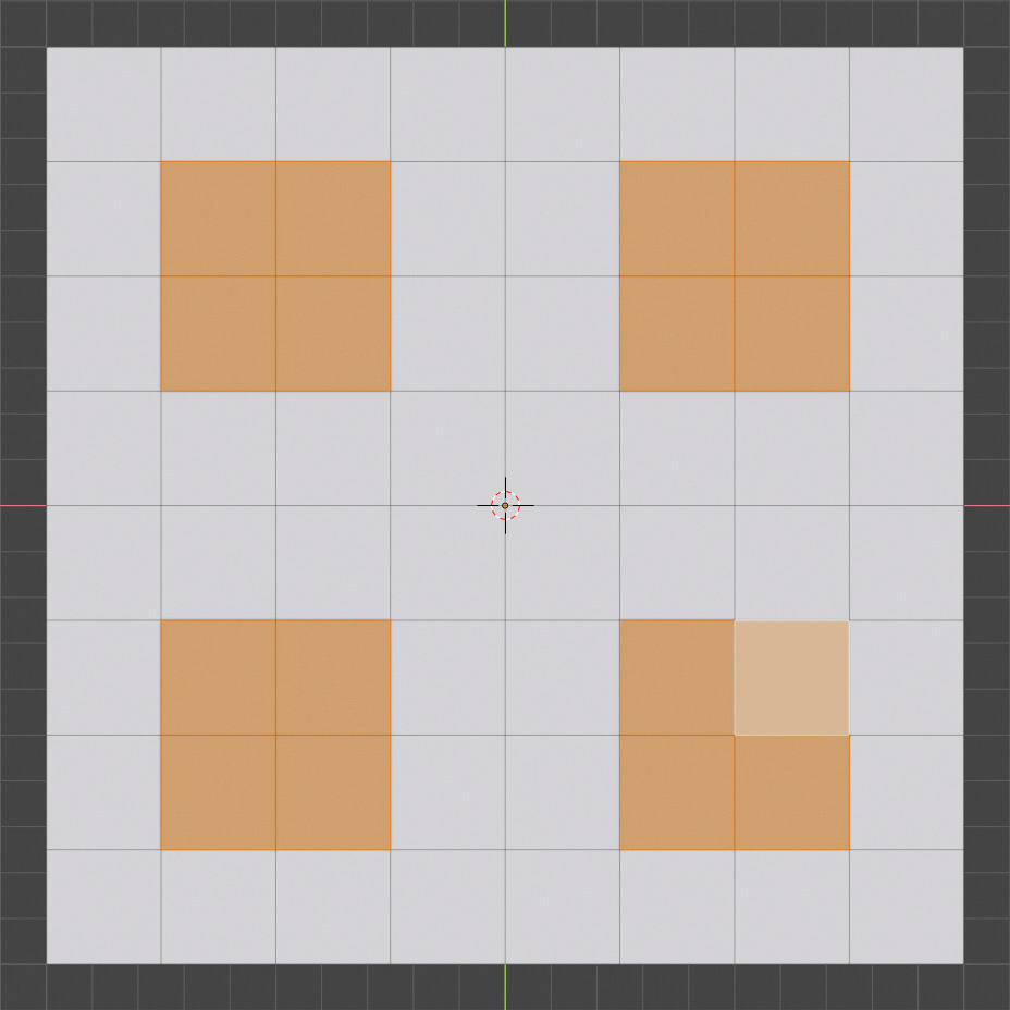
Let’s start with a practical example regarding the use of an armature to animate the model that covers it. Instead of using the classic humanoid figure that you can easily import from the MakeHuman software, we start from the primitive plane divided into 7 cuts (subdivide > number of cuts) by extruding along the z axis (height equal to two blender units) the selected faces as in the image:
With the Loop Cut & Slide, we will divide the columns into seven vertical parts (one at a time), finally applying the subsurf modifier with two divisions.
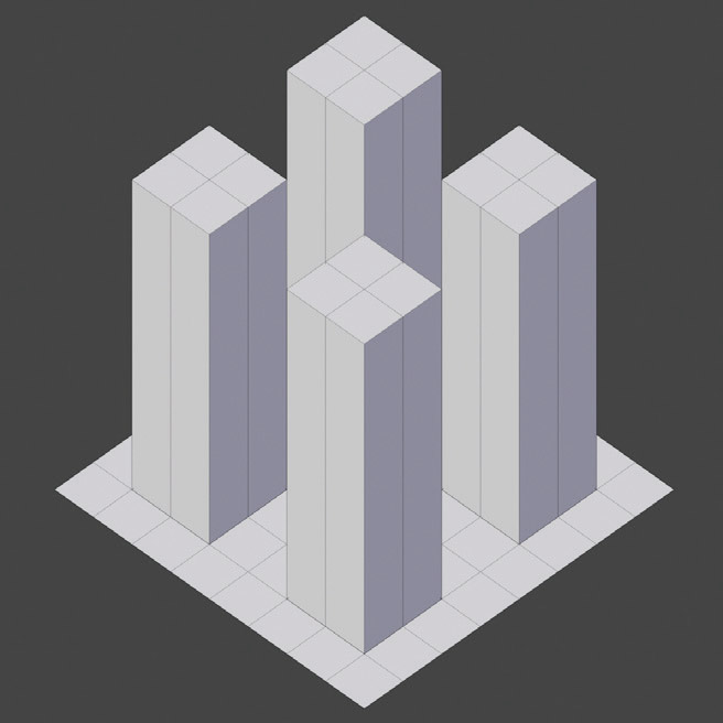

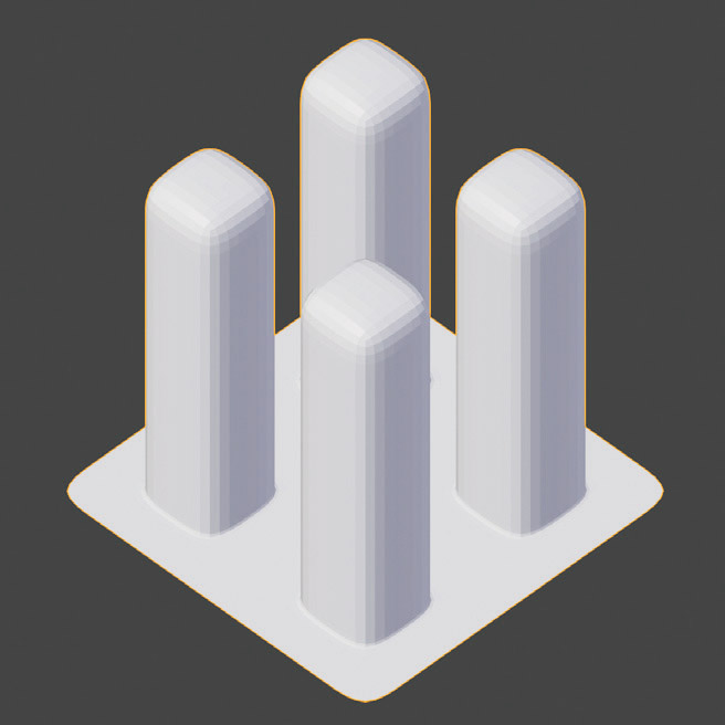
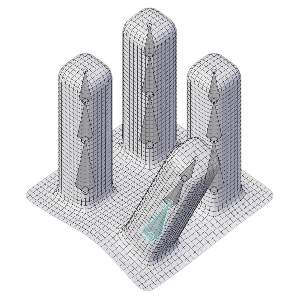
At this point, you need to create an armor of four separate chains, each consisting of three bones that you should position as in the following figure, that is, inside the model.

To always make the armature visible, just activate the In Front checkbox in the Viewport Display panel of the Object Data context.
Now let’s proceed to what is called Skinning by parent the mesh to the armature. So we select the mesh and then the armature, then with Ctrl-P we call up the Set Parent To menu.
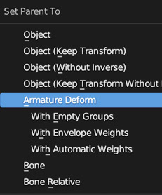
The options that interest us are the Armature Deform: all three choices will automatically create as many Vertex Groups as there are bones in the armature; groups of vertices that can be:
- Empty (With Empty Groups)
- Chosen from those included in the action area set with the envelope display (With Envelope Weights)
- Automatically chosen by Blender (With Automatic Weights) through a powerful algorithm that also decides the weight to be assigned to each vertex in order to obtain natural and continuous deformations.
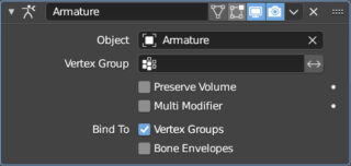
Let’s start with this last option. After parent the mesh to the armature, select the mesh and go to the modifiers context of the properties, where we will immediately notice the presence of the Armature modifier.
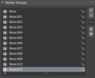
In the Object Data context, we find groups of vertices created by Blender with the names of the bones belonging to the armor. In many cases it is better to assign names to each bone (e.g., head, neck, shoulder, etc.) in advance in order to easily find them in the list.
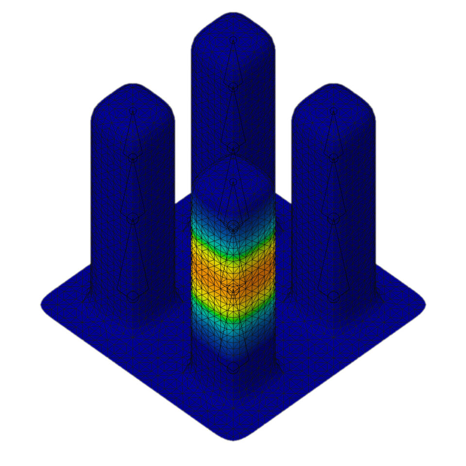
After selecting the entire mesh in weight paint mode, we click on a group/bone in the previous list to see the area of influence of the bone on the mesh and the weights of each individual vertex.
At this point, we just need to select the armor and switch to pose mode, where we will select a bone by right-clicking on it in order to rotate (or scale) it in any direction. We will then see the mesh deform naturally and adapt to the pose of our armor.
If we reselect the mesh in weight paint mode, we will see how the deformation has exactly followed the weights defined by Blender (which we can also adjust to meet our needs).

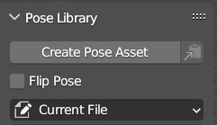
You can create a library with different poses from the sidebar of the 3D View in Pose mode, in the Animation tab: you just need to select all the bones (press A) and click on Create Pose Asset in the Pose Library panel.
We can animate everything as desired using the usual keyframes, both for individual bones and for the entire bone selection. In pose mode, in the Bone context, in the Transform panel, we have the possibility to lock the rotation and scale transformations for each bone on the three axes, as well as translations (for bones not connected to others).
Next paragraph
Previous paragraph
Back to Index
Wishing you an enjoyable and productive study with Blender, I would like to remind you that you can support this project in two ways: by making a small donation through PayPal or by purchasing the professionally formatted and optimized for tablet viewing PDF version on Lulu.com