
After seeing the overview of the nodes that can be used in creating materials, let’s delve into their operation. To insert nodes into the Shader Editor, simply go to the Add menu at the top, where you will also find a Search box for quick search of the desired node.
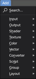
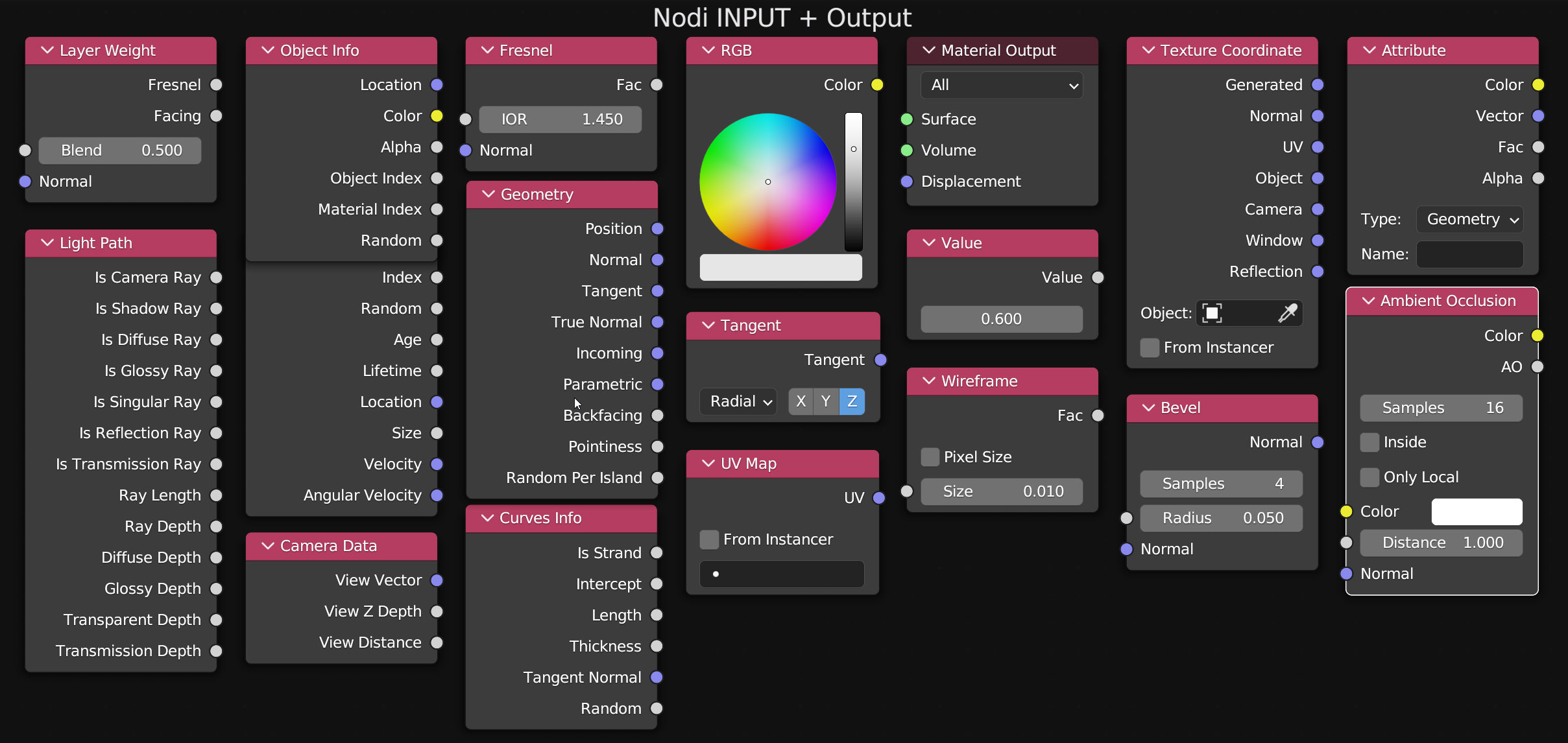
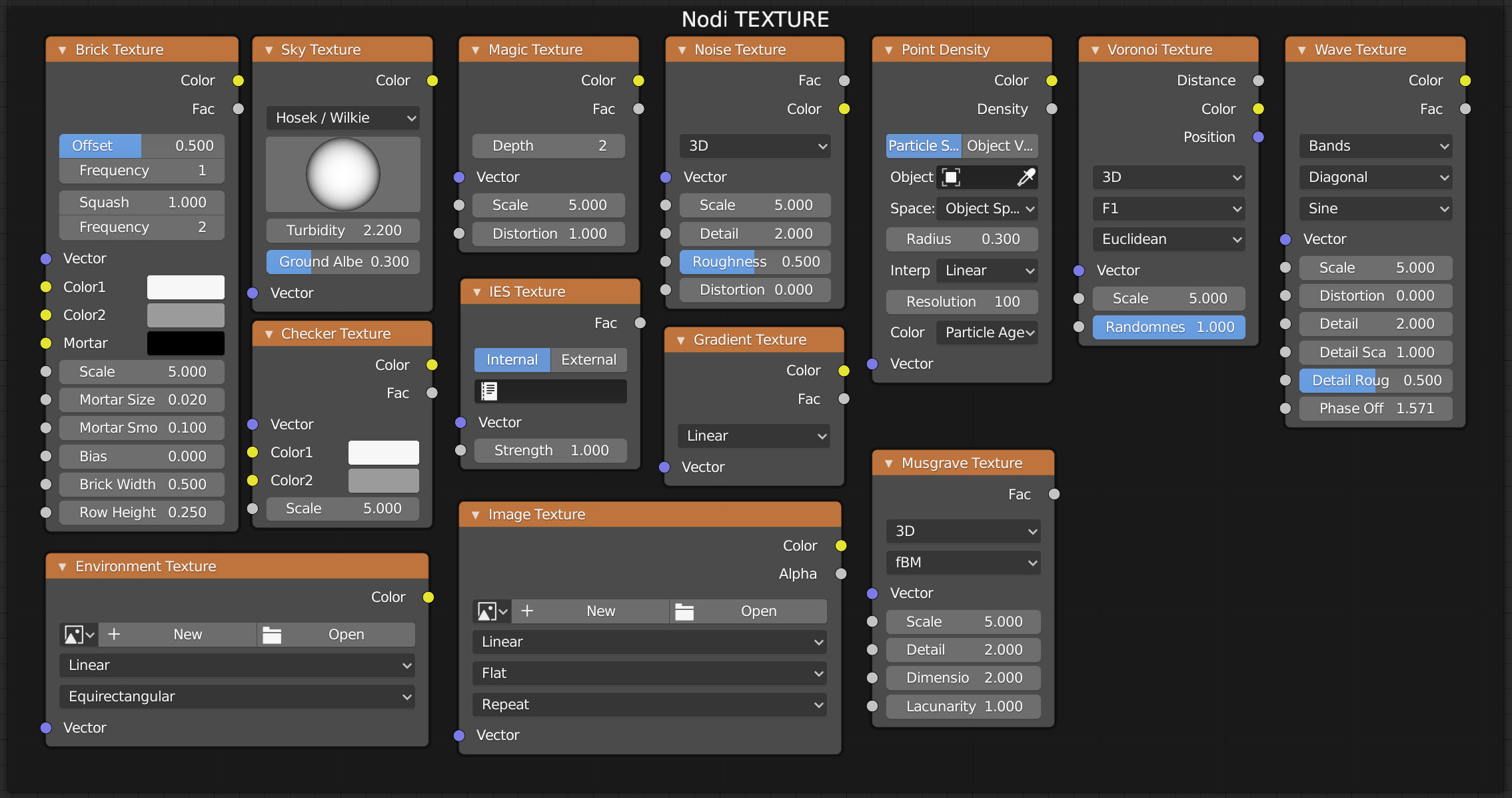
Nodes are mainly divided into the categories: Input, Shader, Texture, Color, Vector and Converter, each of which is assigned a different color. Don’t worry about the huge number of nodes available, which may seem complex at first glance, as we will only cover those that are truly essential to defining high-level materials in the following paragraphs.
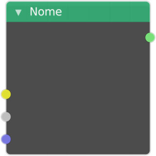
At the top of the node, we find the header with the name and the color corresponding to the category to which it belongs. In the various nodes we will find different combinations of sockets (the colored circles) on both the left side (input) and the right side (output). The sockets indicate that four types of information enter and exit the nodes:
- Yellow – Color data (RGB)
- Gray – Numeric data
- Blue – Vector element data
- Green – Shader data
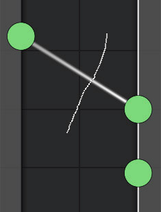
Connections between nodes are created by clicking with the left mouse button on the output sockets (right side of the node) while holding the pressure and moving towards the input sockets of another node.

Output sockets can be connected to multiple input sockets, while the latter will always be connected to a single output socket.
Connections between nodes (threads) generally involve sockets of the same color and can be represented by white lines, or curves (just go to the user preferences, Themes> NodeEditor and change the Noodle Curving value to zero for segments or 4 for curved shapes). Only in cases where a green output socket is not connected to a same-colored input socket, the link becomes red indicating the error. By clicking on an already connected input socket (also in this case holding down the left button) we can disconnect the thread and place it on another input socket.
With the Ctrl combination and continuous right mouse button pressure, the cutter is launched to delete one or more Threads.
In the Shader editor window, the general principles of Blender for manipulating the elements present there apply. By clicking on a node (left button) it will be selected and its perimeter will become white. With the shift key you enable multiple selection. The white color indicates that the node is the active one of the selection, otherwise the outline color becomes amber. When two nodes are not selected, the links that connect their sockets take on the color of the same. By holding down the left mouse button (or simply pressing the G key) you can move the selection within the window. With the right mouse button, the Node Context Menu will appear.
Keyboard commands:
- Shift-D node duplication
- X node deletion
- B start square selection area
- A select all
(click on the background of the node editor to deselect)
With the mouse wheel you can zoom in on the node editor layout, while pressing the same wheel will start the layout panning. If you love order and want the nodes to be well aligned with each other, you can use Snap to Grid, which works in a very similar way to what was seen in the 3D view. In this case, just activate the magnet icon ![]() located at the top right in the Shader Editor header.
located at the top right in the Shader Editor header.
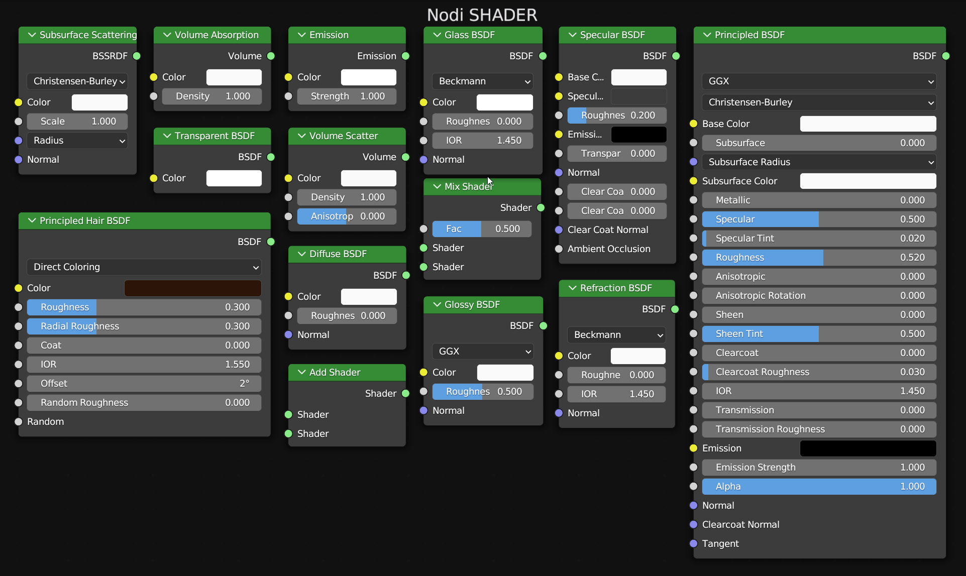
The horizontal dimensions of individual nodes can be increased (but not unlimited) by moving the pointer to the left or right side of the same where it will change to the classic double arrow. The only node that must always be present in the creation of any material is the Material Output node (colored red like those in the Input family).
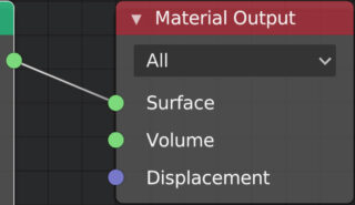
Whatever the combination of nodes in a material, it must end with at least one connection to the green socket (surface or volume) of the Output node.
Let’s now look at these two nodes:
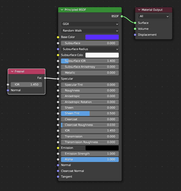
We see that the only output socket of the Fresnel node (input category) is connected to the specular socket of the Principled Shader. The gray color of the sockets ensures that a numeric value will arrive in specular, as seen in the previous paragraph. However, this value will not be fixed, but will depend on both the index of refraction IOR (if different from 1) of the Fresnel node and the camera angle relative to the surface points treated by the shader. The IOR in question should not be confused with the one present in the Principled Shader regarding rays passing through transparent surfaces (as we will see shortly). With the Fresnel node it is possible to simulate the homonymous effect according to which the reflection of the surrounding environment by glossy or metallic surfaces depends on the angle of impact of the light rays on them.
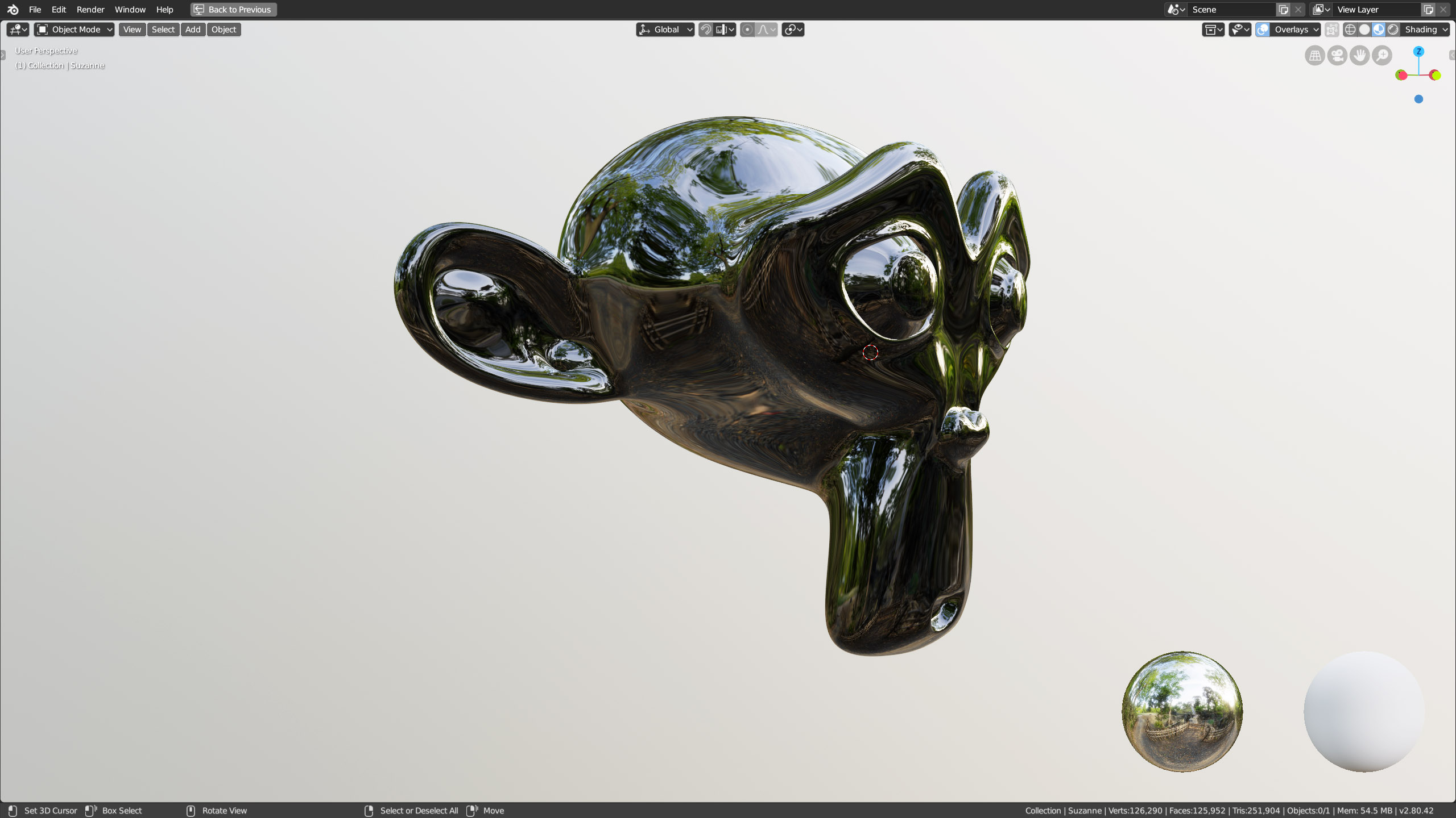
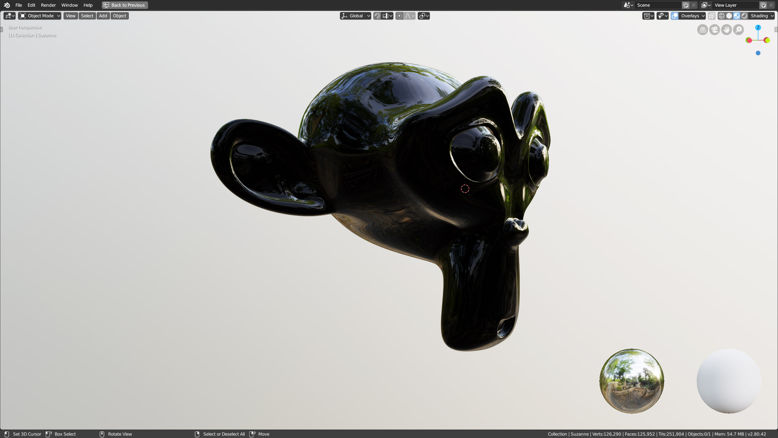
In the images above, we see first a reflection with a fixed specular value of 1, and then the same reflection governed by the Fresnel node. In the second case, it is possible to notice that the reflection becomes brighter and more evident in the vicinity of the outline of the figure. If the intent were to obtain a completely photorealistic image, then the use of the Fresnel node might be indispensable. You can easily find IOR values for many types of materials on the internet. The one just seen is a practical example of the operation of gray-colored sockets. We will analyze some specific uses of yellow, green, and blue sockets later. At this time it is completely useless to analyze the various nodes one by one, since we will see many of them in action when dealing with other topics such as Textures.
We already know the Specular and Metallic properties of the Principled Shader.

Anisotropic, Sheen, Sheen Tint have no effect in Blender Eevee, while the effect of Clearcot is negligible. Emission will be treated in the chapter dedicated to Cycles. Let’s therefore analyze the remaining fundamental properties of the node, namely: Transmission and Sub Surface Scattering. By activating Transmission, light rays will pass through the surface according to an index of refraction. Let’s set the maximum transparency of the material by setting the transmission value to one. Then go to the Material context of the properties, icon ![]() and check the Screen Space Refraction box in the Settings panel.
and check the Screen Space Refraction box in the Settings panel.
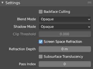
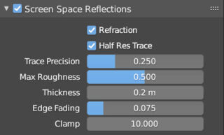
To finish, activate the Screen Space Reflections panel in the Render context of the properties by checking the Refraction box.
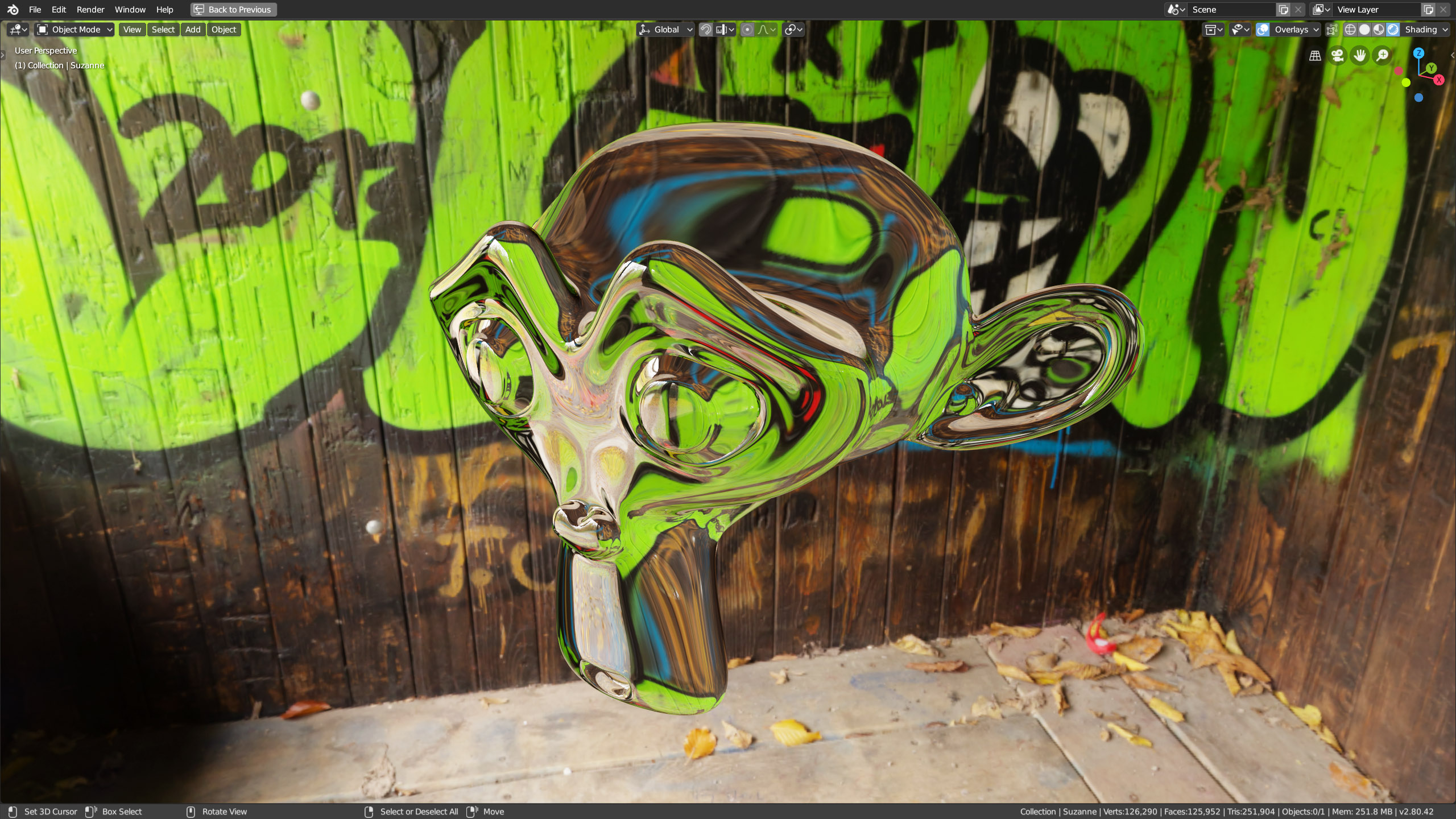
In this way, the mesh allows you to see what is behind it, whether it is an HDRI background or any other renderable object. Transmission makes the material similar to glass with a reflection of the environment no longer influenced by the Specular parameter (although the Specular Tint continues to work). Here is a list of typical IOR values depending on the material to be simulated:
Air (pure transparency) 1
Water 1.333
Amber/Quartz 1.550
Crystal 1.870
Ice 1.310
Diamond 2.417 – 2.541
Jade 1.660 – 1.680
Transparent plastic 1.4
Ruby 1.760 -2.419
Silicone 4.0
Emerald 1.576 – 1.582
Topaz 1.620 – 1.627
Glass 1.4 – 1.9
Thin glass 1.450
Thick glass 1.650
Standard glass 1.520
Sapphire 1.760
Sugar 1.560
The Principled Shader offers the simulation of the physical phenomenon known as Sub Surface Scattering (SSS) regarding the sub-surface light propagation in translucent objects. For some materials, this phenomenon is so evident that it cannot be neglected by rendering that aspires to a certain realism, including Eevee. Some typical examples are: human skin, wax or fruit. In Subsurface Color it is possible to choose the hue of the light that spreads under the surface according to the material and its base color. First of all, let’s look at the panel dedicated to SSS that you will find in the Render context of the object properties.
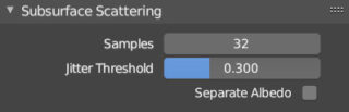
The simulation will improve as the value in Samples (32 is the maximum) and Jitter Threshold increases.


In the images above you can see the difference between a material without and with SSS. To make the effect more easily observable, I inserted a point light behind the mesh. In Eeevee, we just need to act on the Subsurface (intensity) and Subsurface Radius parameters of the Principled node, choosing a Subsurface Color. The remaining Subsurface IOR and Subsurface Anisotropy parameters will be used with the Cycles engine.
Blender allows you to assign all the materials you want to a mesh; you just need to add the various slots by clicking the + button in the material context, select one and start creating the new material with +New.
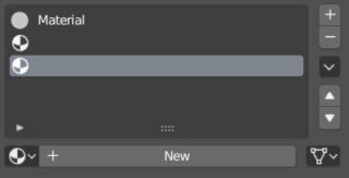
Obviously, we cannot expect a single face of a mesh to have two different surface materials at the same time, but it is possible to assign different materials to distinct groups of faces, up to rendering as many materials as there are faces on the mesh simultaneously. In edit mode, first we will select the parts of the model to which we want to apply a particular material chosen from the list, finally completing the operation with a simple click on Assign.
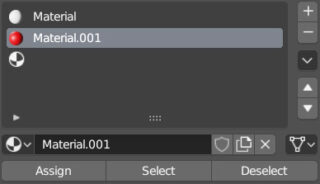
The Assign, Select, and Deselect keys only appear in edit mode. Later, it might happen that you want to select only the faces of the mesh to which one of the materials in the list has been applied; in that case, just highlight the material and click Select. Deselect, on the other hand, deselects all the faces (eventually selected) having the material highlighted in the list.
Next paragraph
Previous paragraph
Back to Index
Wishing you an enjoyable and productive study with Blender, I would like to remind you that you can support this project in two ways: by making a small donation through PayPal or by purchasing the professionally formatted and optimized for tablet viewing PDF version on Lulu.com