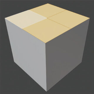
Let’s start by making the geometry of the cube more complex by editing it in edit mode. First, we select a single face of our choice and start the Subdivide tool, which is the first option in the Context Menü (vertex, edge, face – right click). Subdivide acts on each individual element of our selection of edges or faces. When dividing one or more faces, they will initially be divided into four parts geometrically consistent with the initial shape, in this case four squares.
Upon starting Subdivide, a new panel with all the options for the just completed division appears at the bottom of the 3D View.
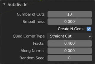
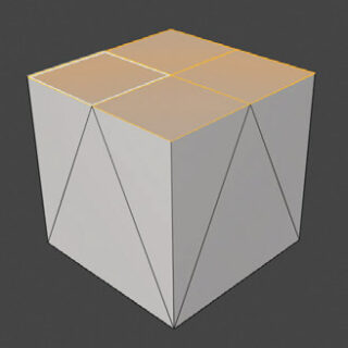
It will disappear either by performing a different operation on the model or by switching to object mode. In the Numbers of Cuts field, you can type the maximum number of cuts and vary it using the mouse from zero to that number. If you uncheck the Create N-Gons box, the faces of the cube that were not divided will change so that they are composed of triangles whose vertices coincide with those created by the division, thus avoiding the formation of polygons with n>4 vertices.
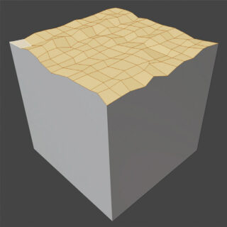
Fractal introduces random noise in the division in order to obtain irregular surfaces. With Smoothness, you can soften the jaggedness of the result of the fractal and non-fractal division. You can experiment with the fractal division options right away:
- Fractal (intensity of irregularity)
- Along Normal (we will see shortly what a normal is)
- Random Seed (to obtain different and random results)
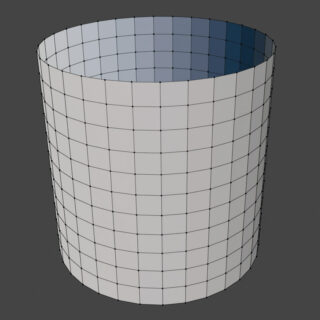
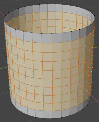
The subdivision process does not only affect the faces of a mesh, but also acts on any selection of edges, each of which is initially divided into two smaller segments. For example, if we apply one or more subdivisions to all the faces of the primitive Cylinder, we will get this result:
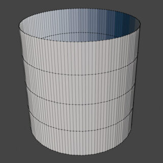
On the other hand, if we select and subdivide only the vertical edges of the surface (increasing the number of cuts to our liking), we will get a very different result from the previous one, which in certain situations may be exactly what we want.
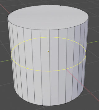
Let’s introduce a different method for dividing surfaces, which in this case allows us to achieve the same result in a much simpler way (without having to select anything on our mesh): the useful Loop Cut & Slide tool. Let’s start again from the undivided cylinder and click on the icon (Ctrl-R) ![]() . By positioning the pointer on the cylinder (anywhere, except the top and bottom edges), we will see a yellow line appear at the midpoint of its height, which represents the minimum division.
. By positioning the pointer on the cylinder (anywhere, except the top and bottom edges), we will see a yellow line appear at the midpoint of its height, which represents the minimum division.
By confirming the operation with the left mouse button, we can subsequently vary the position of the cutting line using the mouse (and confirm again with the left mouse button) or leave it as it is by pressing Esc. This will bring up the panel:
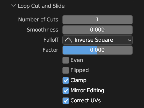
where you can increase the division to your liking with the Numbers of Cuts field
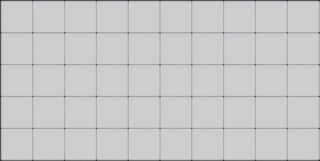
The Factor parameter allows you to translate the set of edges obtained. Feel free to experiment with the smoothness option to shape the division. Of course, the Loop Cut does not only act longitudinally as in the case of the cylinder, but also in the opposite direction. For example, take a plane with one of its dimensions (x) double the other (y). Start the Loop Cut and first divide along the x axis (by bringing the pointer to the relevant edge) by an odd number Sx, and then along the Y axis by a Sy = (Sx-1) / 2 and here is the plane divided into perfect squares:
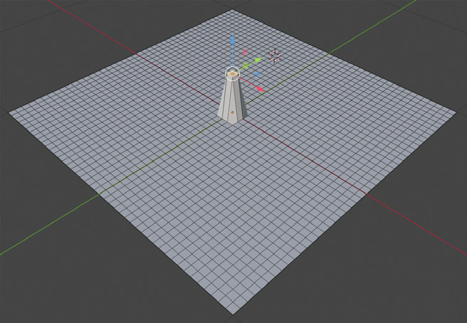
Blender offers some important functions that regulate the behavior of transformations on multiple selections of faces/vertices, with which it is possible to create some particularly interesting surfaces. Let’s start again from the primitive Plane, which we will divide in Edit Mode until we get a reasonable number of vertices. Select any face from those present and translate it upwards with the G key followed by the Z key, or through the appropriate manipulators. We will see the geometry of the mesh deform with the formation of a protrusion similar to a spur.
This happens because the translated face remains part of the overall mesh, unless it is specifically deleted or separated from the object, or “extruded” (we will see later what extrusion is). The separation of a selection of faces from the original model occurs by choosing Selection from the Separate menu that appears on the screen with the press of the P key.
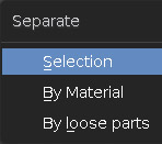
Separate by loose parts divides the selection according to already disconnected parts, perhaps derived from a previous join of two meshes with the Join function. By Material separates the parts of the mesh with different materials (paragraph 3.12). The separated part will continue to be visible in edit mode, although it becomes a new object in the scene whose name remains the same as the original mesh, with the addition of a numerical suffix ![]() .
.
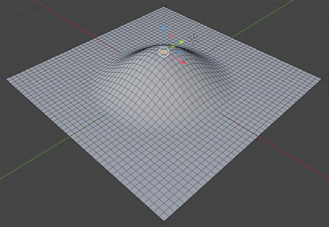
Returning to the image of the plane with a single raised face, we notice that all the contiguous faces are severely deformed, as the vertices in common with the translated face have also been translated along the Z axis. Let’s see how to propagate the influence of any transformation (Move, Rotate, Scale) to the faces of the model that are not directly selected, using the options of Proportional Editing, which can be accessed through the following icon in the 3D View header ![]() . First, we activate the Proportional Editing by clicking on the circle icon, which will turn blue (we are still in edit mode). The icon next to it
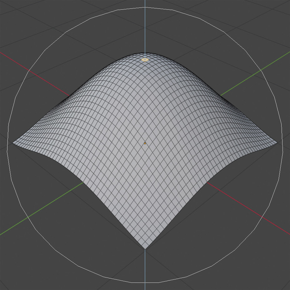
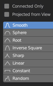
. First, we activate the Proportional Editing by clicking on the circle icon, which will turn blue (we are still in edit mode). The icon next to it ![]() indicates the influence profile that the transformation will have on the part of the mesh that is not selected (clicking on it will show you the remaining profiles). Repeat the same previous action (translate a single face) this time with proportional editing enabled, obtaining this result.
indicates the influence profile that the transformation will have on the part of the mesh that is not selected (clicking on it will show you the remaining profiles). Repeat the same previous action (translate a single face) this time with proportional editing enabled, obtaining this result.
Starting the transformation with the keyboard shortcuts (For example: S+Z), we can modify the range of the sphere of influence, represented on the screen by a gray circle with a default diameter of one metric unit. Radius to be increased or decreased via the mouse wheel.
During any transformation, the header of the 3D View changes, showing in real time the data of the transformation itself: displacement in metric units, rotation in degrees, scale change; with the additional data on the size of the sphere of influence (proportional size) in the case of active proportional editing.
![]()
By default, the profile used for proportional editing is Smooth, which as we have seen is used to create smooth protuberances. You can repeat the operation with all the other methods to realize the usefulness of this modeling technique, obtaining different results that will certainly stimulate your imagination.
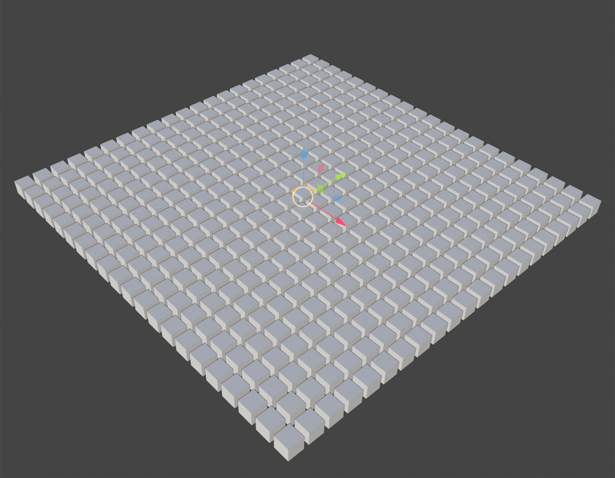
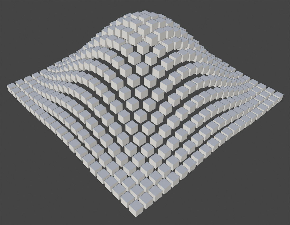
By activating Connected Only, we will restrict the effects of the transformation to the faces inside the area of influence that are connected to each other in a chain along a path that is also inside the sphere seen earlier. Although we introduced proportional editing in edit mode, where it is most often used, it is still valid for any multiple selection of objects in object mode. In the images next to it, we see it in action on a grid of cubes (Array modifier).
Next paragraph
Previous paragraph
Back to Index
Wishing you an enjoyable and productive study with Blender, I would like to remind you that you can support this project in two ways: by making a small donation through PayPal or by purchasing the professionally formatted and optimized for tablet viewing PDF version on Lulu.com