
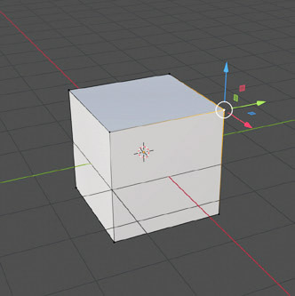
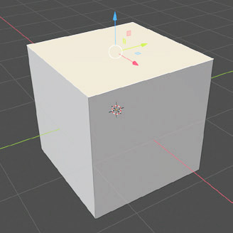
We select the default scene cube and switch to Blender’s Edit Mode. The Tab key is reserved for quickly switching between Object Mode and Edit Mode. Of course, you can also use the appropriate selector ![]() placed on the left side of the 3D View header to choose the desired mode. When a primitive is displayed in Edit Mode for the first time, all of its faces, edges, and vertices are highlighted and selected. Otherwise, we will find the selection with which Edit Mode was previously closed. In the toolbar, we notice the appearance of many tools (visible on the left) that we will have the opportunity to delve into in the next chapter. In Edit Mode, the 3D View header appears slightly different, especially due to the appearance of these buttons
placed on the left side of the 3D View header to choose the desired mode. When a primitive is displayed in Edit Mode for the first time, all of its faces, edges, and vertices are highlighted and selected. Otherwise, we will find the selection with which Edit Mode was previously closed. In the toolbar, we notice the appearance of many tools (visible on the left) that we will have the opportunity to delve into in the next chapter. In Edit Mode, the 3D View header appears slightly different, especially due to the appearance of these buttons ![]() which enable the selection of vertices, edges and individual faces of the object, respectively (from left to right). Vertex and edge selection is done by clicking on each with the left button, or in their vicinity. Faces are selected by clicking anywhere on their internal point. When the display is in wireframe mode, the
which enable the selection of vertices, edges and individual faces of the object, respectively (from left to right). Vertex and edge selection is done by clicking on each with the left button, or in their vicinity. Faces are selected by clicking anywhere on their internal point. When the display is in wireframe mode, the ![]() icon in the 3D View header, and/or when transparency mode is active, the
icon in the 3D View header, and/or when transparency mode is active, the ![]() icon, the faces will become selectable by clicking near the square depicted inside them. Selected vertices are displayed as white points, in which case Blender also highlights part of the edges that include the selected vertex.
icon, the faces will become selectable by clicking near the square depicted inside them. Selected vertices are displayed as white points, in which case Blender also highlights part of the edges that include the selected vertex.
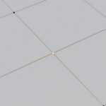
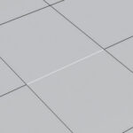
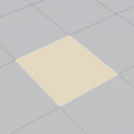
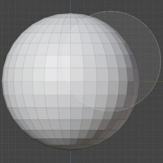
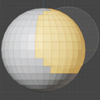
In the following images, we see the selection for edges and the selection for faces.
Once the element is selected, it can be manipulated in a similar way to what we saw for objects in Object Mode. The selected vertex can be moved to any position in space, and the geometry of the object will adapt in real-time to this movement. Since it is a one-dimensional geometric point, transformations such as rotation (R key) and scaling (S key) will not have any effect on it. The vertex can, however, be duplicated (Shift-D) to obtain one or more isolated vertices. Deleting a vertex (X key) will also delete the edges to which that vertex belongs and, as a result, the faces that include those edges. The edge is a two-dimensional segment delimited by two vertices and can be moved in any direction, or resized by changing its length, or rotated around all axes other than the one passing through its two vertices. Deleting an edge will remove all faces that include that edge. The face is a polygonal plane figure with N vertices. In 3D modeling, triangular and quadrilateral (quad) faces are mainly used as elementary components of surfaces. Blender also handles polygonal faces with more than 4 sides (called Ngons). A face can be rotated, scaled, and moved to any position in space. Deleting the face will leave both the vertices and the edges shared with other faces in the model in place.

The Edit Mode allows you to work on all models selected at the time of its start, and it is not possible to interact with other elements of the scene although they are visible in the 3D View. When inserting a primitive in Edit Mode, it becomes an integral part of the active object being processed. 3D models are made up of a relatively large number of faces (triangular, square or ngons) and are therefore called Mesh. Although in Blender all elements of the scene are defined objects, from now on we can refer to 3D models as meshes, and it is precisely for these that we have the Edit Mode available. So far, we have selected a single element at a time, whether it was the mesh in Object Mode or a vertex/edge/face in Edit Mode. To select multiple elements of the scene simultaneously, or multiple vertices, edges, or faces of a mesh, just hold down the Shift key while clicking on each of them with the left mouse button. With or without selected elements, you can select everything with the A key (while a quick double press of A will deselect everything). As seen on page 14, the default selection mode is Box, which means that by holding down the left mouse button, you can define a rectangular area and select all elements within it (in this case, those already selected within the rectangle will remain so). You can also start a square selection area with the B key. With the C key, you will launch a circular selection area whose size can be adjusted with the mouse wheel. Pressing the left mouse button will select the elements within the circle, while pressing the mouse wheel will deselect them.
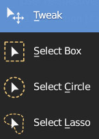
In many cases, it is essential to select the inverse of the current selection using the Ctrl-I combination, or by selecting Invert from the Select menu in the 3D View header; this will result in all elements of the model that were initially deselected being selected. In the Select menu, you will also find other interesting selection methods (including Random) that may be useful during modeling or in organizing elements within the scene. For even more comprehensive control over selection operations, you can use the add, subtract, etc options in the main header (the default active Tool Settings panel, but can be disabled from the View menu) after selecting the selection mode from the toolbar with a slightly prolonged click on the icon

this will bring up the window with the selection modes described above, plus Select Lasso, which allows you to draw a selection area on the screen, which is very useful when you need to select a certain number of elements while excluding others nearby.
Selecting two vertices highlights and selects the segment connecting them. Selecting all the vertices of a face also selects the face itself along with its vertices.
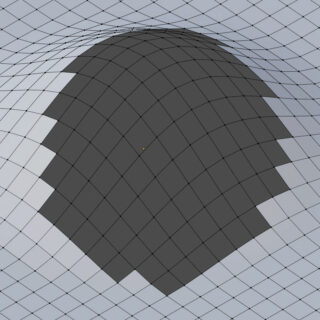
In 3D Solid graphics representation, only elements visible in the foreground are selected, not those hidden. To select all elements within the selection areas, both square and circular, regardless of their depth, it is necessary to activate the X-Ray button (already seen before) ![]() in the 3D View header or otherwise switch to Wire Frame display (which will automatically activate the previous button)
in the 3D View header or otherwise switch to Wire Frame display (which will automatically activate the previous button) ![]() . If the selection concerns faces, then the dots inside them must necessarily be included by the selection tools (box, circle and lasso) in order for the faces to be selected.
. If the selection concerns faces, then the dots inside them must necessarily be included by the selection tools (box, circle and lasso) in order for the faces to be selected.
There are four viewport shading modes for the 3D View in total. At the moment, we will mainly work in solid and wireframe, the other modes will be covered in more depth in later paragraphs/chapters. For each mesh, it is possible to differentiate the shading in the 3D preview from the general setting adopted for the viewport; this is thanks to the Viewport Display panel in the Object context of the properties, accessible by clicking the icon ![]()
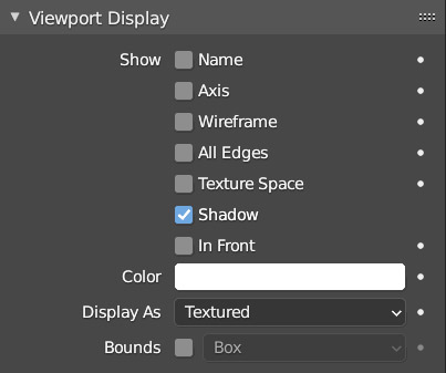
Through Display As, it is possible to decide the maximum display type that an object will have in the 3D preview. For example, choosing Wire, the mesh will appear in wireframe even if the general setting of the 3D View is solid. Checking the wireframe box in solid mode, we can see the edges of the mesh drawn with black lines on the model. If some edges are not visible, you will also need to activate All Edges.
To delete one or more elements of the mesh, whether they are vertices, edges, or faces, just press the X button to bring up the Delete menu on the screen where you can decide to delete the vertices, edges, or faces of your selection, always remembering the principle that deleting a vertex also deletes the edges and faces to which the vertex belongs; and that similarly deleting an edge deletes all faces that integrate it.
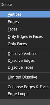
We also have the ability to delete Only Edges & Faces, or Only Faces. With the latter option, the faces are deleted, but the edges and their vertices remain in place.
The Dissolve (vertices, edges, faces) options delete excess vertices, edges, or faces, that is, those elements that do not affect the geometry of the model and that we do not intend to use, such as an orphan vertex aligned with the two ends in a single edge, or an edge on a flat face, etc. The deletion of vertices is often necessary in situations where multiple vertices are coincident or very close to each other, for example after merging multiple meshes into one with the Join command (Ctrl-J). In these cases, Merge by Distance located in the Mesh > Merge > By Distance menu of the 3D View header (always in edit mode) comes to our aid. After selecting the coincident or very close vertices, simply start Merge by Distance and the panel will appear at the bottom of the 3D View.
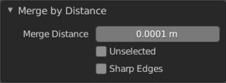
The selected vertices, which are less than the value indicated in Merge Distance, will be joined and the number of vertices removed will appear for a few seconds in the header info at the bottom of the Blender interface (below the timeline) ![]() .
.
With the Merge tool (M key), we can merge the selected vertices in several methods: at the first selected vertex, at the last selected vertex, at the cursor, or cause the vertices to collapse at a midpoint.
By selecting two vertices that do not belong to the same edge, you can define a new edge that connects them with just the F key (fill) and similarly, by selecting three or more vertices (belonging or not to the same plane) with the F key, we will create a face that, depending on the case, can be of type Tri, Quad, or Ngons. In the latter case, it is possible to subsequently transform the face into a set of triangular polygons thanks to the Triangulate Faces and Poke Faces tools located in the Face menu in the 3D view header (Ctrl-F).
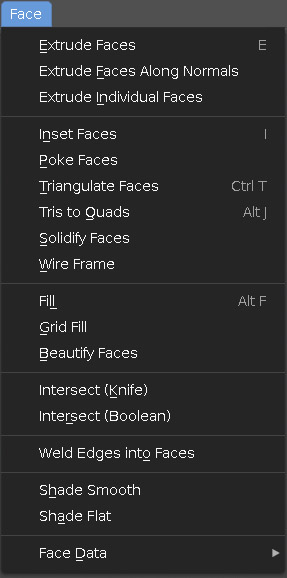
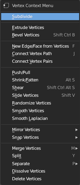
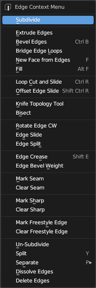
The first algorithm will find the minimum number of triangular faces to fill the surface, while Poke Face will ensure (where possible) that all these faces have a vertex in common at the geometric center of the surface defined by the Ngons. The Faces menu is full of options that may be very useful in the modeling process covered in the next chapter. Depending on the type of element we are selecting (vertices, edges, or faces), clicking the right button in any point of the 3D View in Edit mode will bring up the following three context menus respectively:

Next paragraph
Previous paragraph
Back to Index
Wishing you an enjoyable and productive study with Blender, I would like to remind you that you can support this project in two ways: by making a small donation through PayPal or by purchasing the professionally formatted and optimized for tablet viewing PDF version on Lulu.com