
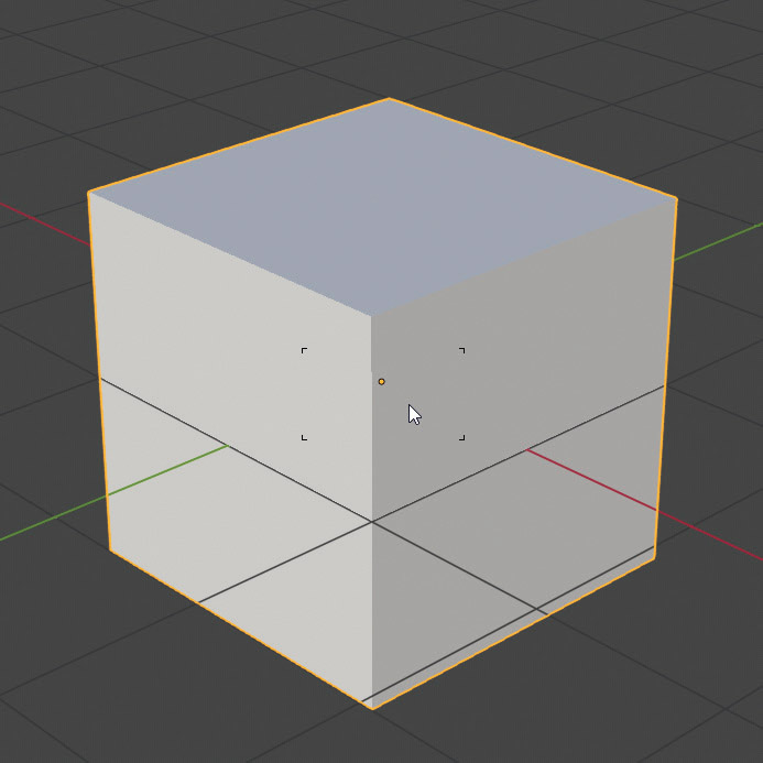
The 3D View is the Blender window where you can insert and modify the various elements of the scene, interacting directly with them within the preview called the Viewport. At startup, the default scene consisting of a single primitive element, the cube, along with a camera and a point light source is visible in the 3D View. You will notice that the icon of an arrow inside a square is active by default at the top left of the 3D View.
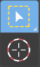
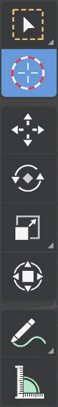
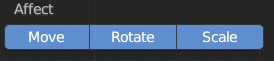
the icon below it, a circle, is inactive (both cannot be active at the same time). The first indicates the selection mode (Box), which means that to select any object in the 3D View, you must click on it with the left mouse button (Shift + left mouse button, or left mouse button on an empty area, to deselect). The selected (active) object is highlighted by an amber border. The two icons seen previously belong to the 3D View Toolbar (which appears/disappears when the T key is pressed). In it, we also find the icons related to the three basic transformations: Move, Rotate, and Scale (from top to bottom).
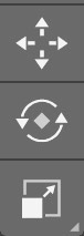
This other icon

instead activates all three transformations listed above.
With the default cube selected, we activate the Move transformation. Three red, green, and blue vectors appear, indicating the orientation for the transformations. By default, these vectors are aligned with the x, y, and z axes that define the Global space; we will see immediately that it is also possible to use a different and important Local space, the one integral with the object.
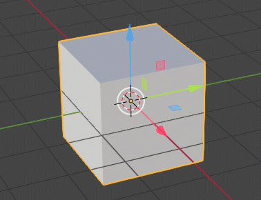
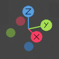
To better understand what this is about, we select the cube and rotate it in 3D space. You can do this by simply pressing the R key and then moving the mouse to rotate the cube around a certain axis (we don’t need to know which one at the moment) and then confirming and completing the rotation with a left mouse click; keeping in mind that the Esc key cancels the ongoing rotation, while the Undo (Ctrl-Z) transformation has already been completed. The orientation for the transformations is chosen by clicking the button: ![]() in the center of the 3D View header, with which the list of available transformations appears: Global, Local, Normal, Gimbal, View, Cursor. The trio of vectors of the Global orientation is always visible in the Gizmo at the top right of the Viewport.
in the center of the 3D View header, with which the list of available transformations appears: Global, Local, Normal, Gimbal, View, Cursor. The trio of vectors of the Global orientation is always visible in the Gizmo at the top right of the Viewport.
In the Global system, the vectors remain fixed regardless of the orientation or rotation of the object. In the Local reference system, the three axes remain anchored to the object during any rotation.
In the View reference system, the blue vector (z) is always directed towards the point of view: a system useful for translating the object along the x and y directions orthogonal to the direction we are looking in. We will address the Normal coordinate system later on.
The type of options present in the 3D View change depending on the mode in use, which is by default the Object Mode, useful for:
- Inserting primitives into the scene
- Transforming the main attributes of any object such as size, position, and orientation in space
- Creating relationships between objects in the scene.
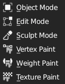
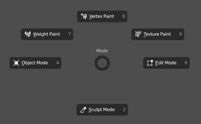
To change the mode, simply click the button ![]() in the header and choose from the menu that appears on the screen. Immediately after the Object Mode, we will explore the fundamental Edit Mode where we can modify the object’s geometry by precisely acting on each individual vertex. In the guide, other interesting modes will also be illustrated, such as the Sculpt Mode, Texture Paint, and Vertex Paint.
in the header and choose from the menu that appears on the screen. Immediately after the Object Mode, we will explore the fundamental Edit Mode where we can modify the object’s geometry by precisely acting on each individual vertex. In the guide, other interesting modes will also be illustrated, such as the Sculpt Mode, Texture Paint, and Vertex Paint.
By pressing the Ctrl-Tab keys, you will start the pie menu which is a way to quickly select various software features, in this case related to the mode of use of the 3D View (we will not use these menus in the guide).
Inside the 3D View, we can work with two different types of 3D visualization: perspective and orthographic; the switch between the two is made with the press of the numeric keypad key 5 (Numpad 5). The perspective view is linked to a specific point in space (the camera) and differs deeply from the orthographic view which, on the other hand, does not depend on a point in space, but rather on a direction (three of which are known as orthographic projections).
Through the orthographic view, it is not possible to “perceive” the distance between two objects because their sizes do not vary according to the space that separates them, which instead happens in the perspective view where the lines parallel to the xy plane (the one on which we would ideally rest our feet in the 3D View) converge at a vanishing point on the horizon, and objects close to the point of view appear larger compared to when they are located at a greater distance. The perspective view tends to behave similarly to the orthographic view when we zoom (increase the focal length) on subjects that are very far away, in these cases it will be difficult to accurately perceive the distance between the objects that appear “flattened”. The orthographic view is considered more technical and therefore useful for modeling without the influence of the distortion derived from the perspective view and the camera settings (par. 3.10).
Persp e Ortho
Regardless of the mode in use, we can quickly switch between some very useful standard views of the Ortho type (images on the left page):
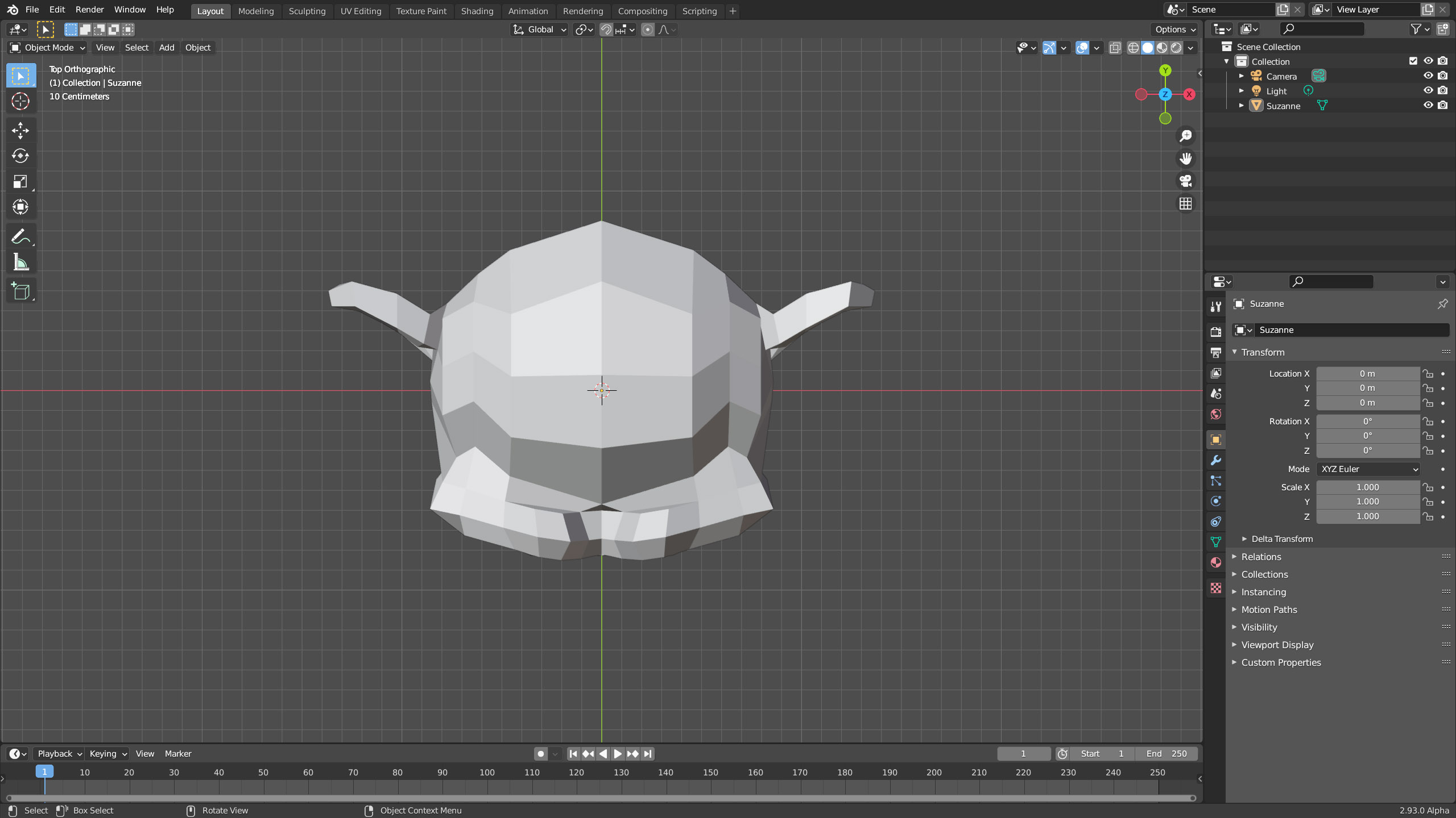
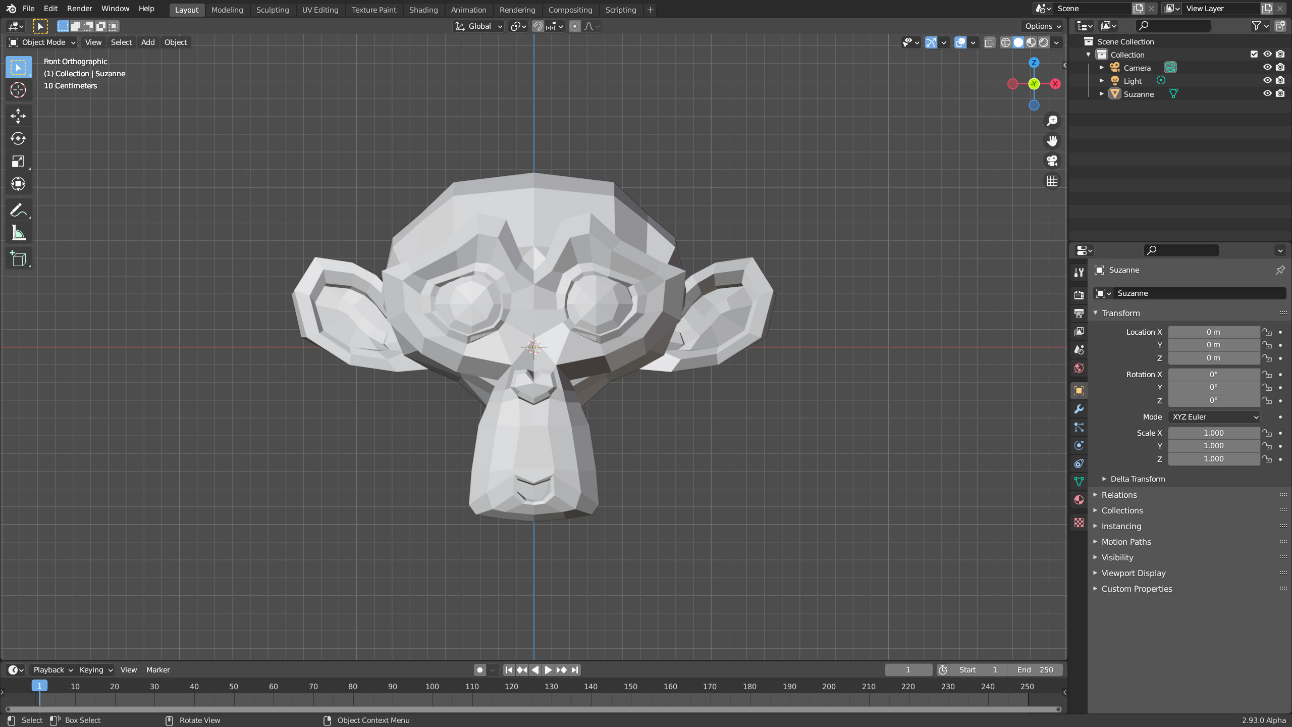
- Top view
numeric keypad key 7 - Front view
numeric keypad key 1 - Right side view
numeric keypad key 3
In addition, by combining the left Ctrl key with the previous keys 7, 1, and 3 (numpad), we will place the view in the opposite directions to those just discussed, respectively:
Bottom view, Back view, Left view. With the remaining cross-shaped keys:

the view can be rotated in 15 degree intervals. To freely rotate the point of view in the 3D scene, hold down the scroll wheel and move the mouse in the desired direction. Once you have found the desired perspective, you can move the point of view closer or further away by rotating the scroll wheel itself. You will soon realize that the rotation of the view is not always centered on the selected object on which you may want to operate; in this case, to center the view on any selected element, simply press the point key (del) on the numeric keypad (or alternatively the / key, which makes any surrounding objects invisible). With the 0 key on the numeric keypad, we will switch from the current point of view in the 3D View to the active camera view in the scene (and vice versa). From the camera’s point of view, we immediately notice the borders that delimit the rendering area from the outside area, which is also visible but darker in color.
The proportions of the border are the same as the resolution chosen in the Output properties context, icon ![]() . For example, if you set the rendering to 1024 x 1024, the border will appear square.
. For example, if you set the rendering to 1024 x 1024, the border will appear square.
To align the active camera and move it so that it frames what we see in the 3D View (free view), use the Ctrl-Alt-Numpad 0 combination. You will find other options related to the camera in the View menu of the 3D view header under the Align View option. In addition to rotating the point of view in the 3D View, there is also the very useful Panning movement, which is activated by pressing the Shift key and the mouse wheel at the same time, along with the movement of the mouse itself to translate the point of view in any direction. The Walk and Fly Navigation modes (View menu> Navigation) are two other methods of navigating within the 3D scene, often useful in finding the ideal perspective for rendering or in the modeling phase. In any view you are in, whether perspective or orthographic (the latter will automatically transform into perspective), you can start the Walk mode which allows you to look around with simple mouse movements, then move forward (in the direction you are looking) with the W key or go backwards with the S key; with the A and D keys, you can move laterally (strafe) and finally with the Q and E keys, you can translate upwards or downwards. Pressing the Tab key activates the force of gravity in order to move in the scene exactly like in video games (however, at least one plane is needed to act as the ground). In Fly Navigation, the concept is similar, but the movement is that of a flight within the scene. You can move with the rotations of the scroll wheel (up and down) that increase and decrease the speed of movement in the direction you are looking, we notice a rectangular area highlighted by its four corners:
by moving the pointer outside of this area, the point of view rotates to frame the scene in the direction of the movement. Pressing the scroll wheel, plus the movement of the mouse, allows you to translate in the directions above, below, left, and right, with faster movements as you move the pointer away from the area. If one of these two modes (walk/fly) is started while you are in the point of view of the active camera, the latter will finally change position and orientation in space. To exit these modes while remaining in the point of view that you have reached through them, just press the left mouse button; with the Esc key, you will return to the initial point of view, canceling everything.
In the top right of the 3D View, we find four icons related to the functionality studied so far.

The first at the top allows you to zoom the 3D view more precisely than with the mouse wheel (this ‘fine’ zoom is also activated with the Ctrl + scroll wheel press + mouse movement combination); the second starts panning; the last switches between the perspective view and the orthographic view.
Let’s conclude this paragraph dedicated to the 3D View by discussing two other elements visible from the first start of Blender: the 3D Cursor and the Grid.
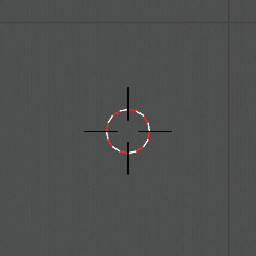
When the tool in use in the 3D View (among those visible at the top) is the cursor, clicking with the left mouse button in any point within the viewport, the 3D Cursor will be placed there.
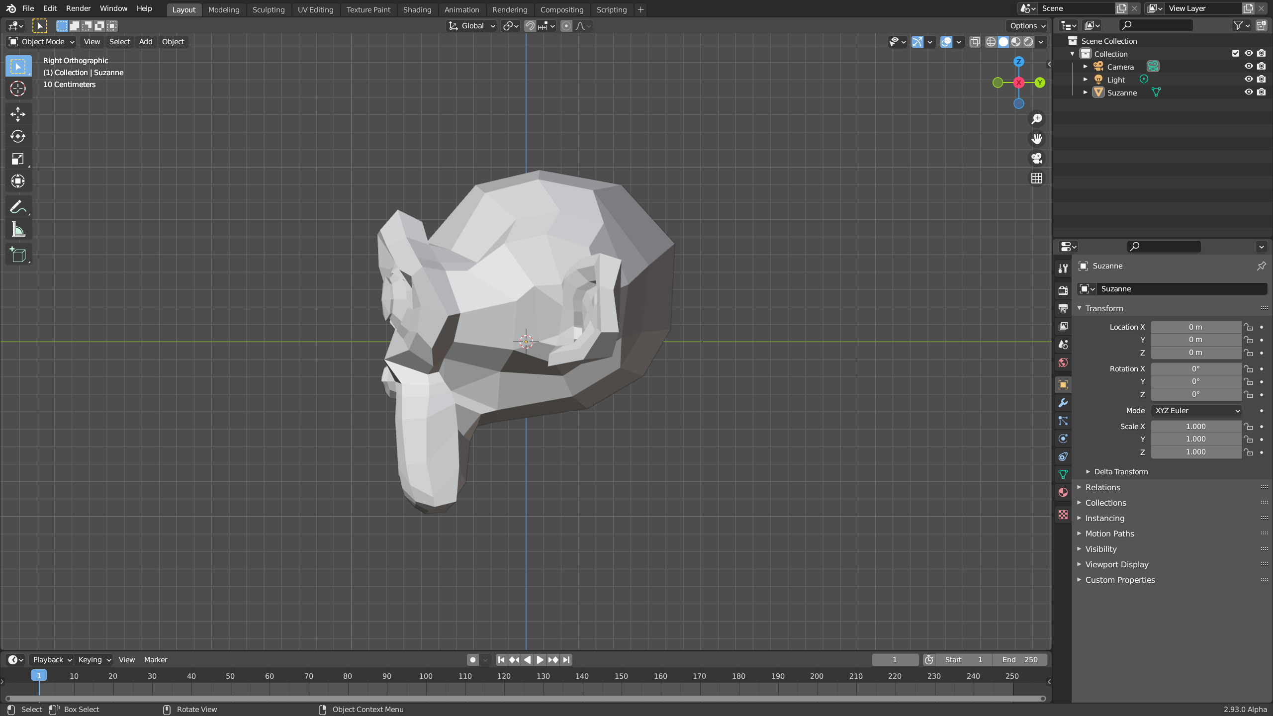
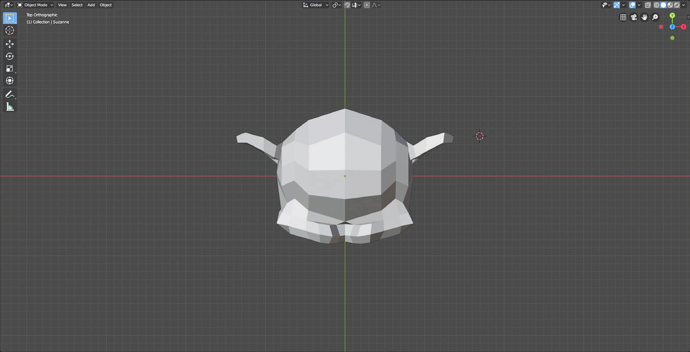
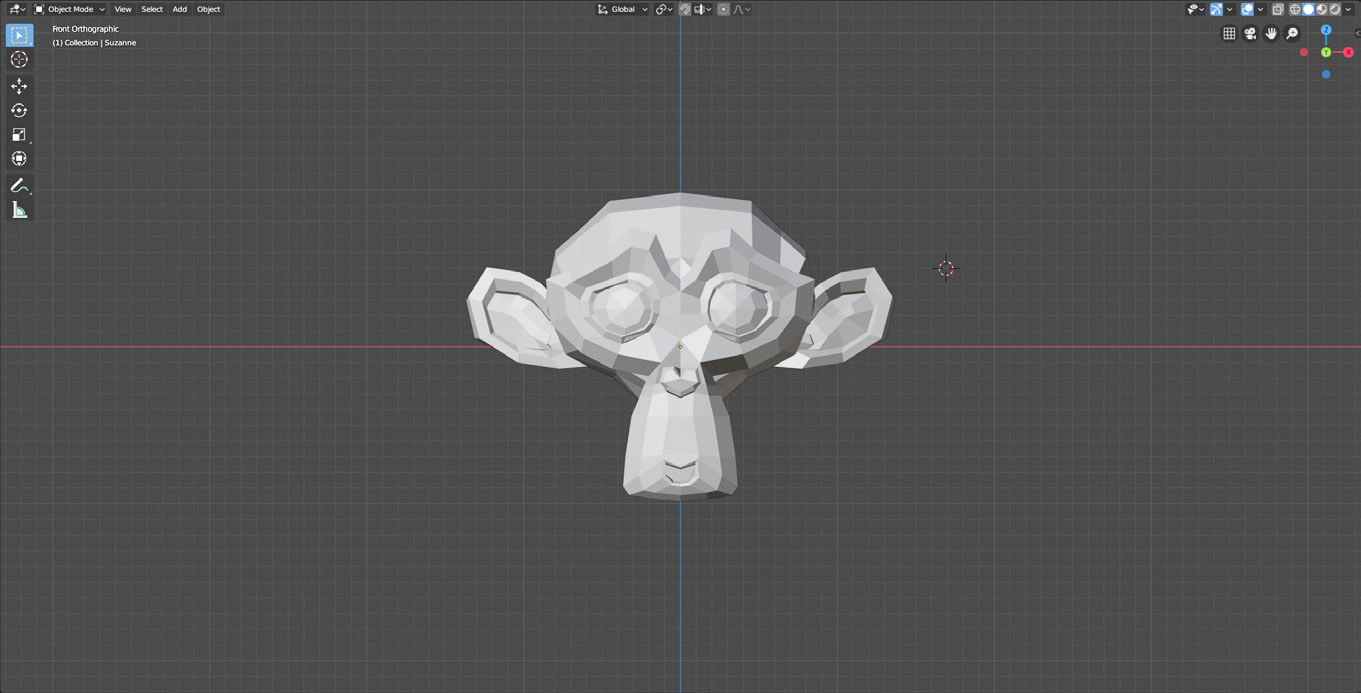
To position the 3D cursor in the desired point (for example, above the ear of the primitive monkey), simply choose the top view in sequence (preferably in ortho mode) and click to position the cursor in the xy plane. Then, we can also determine its position along the z(x) axis in the front view. If we click any point on the model, the Cursor will go to that position exactly, above the surface.
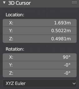
If it is necessary to place the cursor with extreme precision in a point of 3D space, we can act directly on the exact coordinates located in the Sidebar panel that will open on the right side of the 3D View with the press of the N key (we will see that many windows in Blender have important options in the sidebar menu that will always appear on the right with the N key). In the case of the 3D View, the sidebar is divided into three tabs: Item, Tool, and View. In the latter, you will find the coordinates of the 3D Cursor (and also the angles of its rotation in space).
The 3D Cursor is essential for many operations, the simplest of which is inserting any primitive in the desired point of the scene. For precise cursor positioning, we can also use the Grid/Floor system, which appears in the viewport as an infinite grid of squares whose sides are equal to the spatial measurement unit of the 3D World (which by default is the decimal metric system).
From the Scene context, the icon ![]() of the properties, in the Units panel, we can customize the metric system by setting the unit of measure in meters, centimeters, or millimeters.
of the properties, in the Units panel, we can customize the metric system by setting the unit of measure in meters, centimeters, or millimeters.
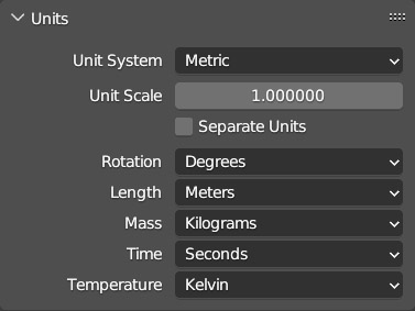
It is also possible to opt for the non-decimal Anglo-Saxon measurement units (inches, feet) or for the zero system, where distances and coordinates are simply expressed by decimal numbers; while as far as angle measurement is concerned, the choice is always between sexagesimal degrees (1°/360°) or radians.
On the right in the header of the 3D view, we find these icons ![]() by clicking on the arrow we access the Overlays menu full of options related to the elements visible in the viewport. Let’s focus for now on the options dedicated to the 3D grid/floor. In addition to being able to disable the view of the grid and the x y axes (z is disabled by default), we find the scale and subdivisions parameters. The grid is only visible in top, front, right, etc. views, and its role is partly analogous to that of the millimeter paper.
by clicking on the arrow we access the Overlays menu full of options related to the elements visible in the viewport. Let’s focus for now on the options dedicated to the 3D grid/floor. In addition to being able to disable the view of the grid and the x y axes (z is disabled by default), we find the scale and subdivisions parameters. The grid is only visible in top, front, right, etc. views, and its role is partly analogous to that of the millimeter paper.
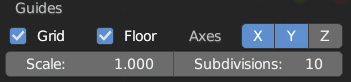
In the remaining free persp and ortho views (those obtained by rotating the point of view), we will see only the Floor represented. To understand the meaning of the Subdivisions parameter, which is set to 10 by default (and not modifiable in the metric system), let’s go to the top orthographic view. By zooming with the mouse wheel (rotation up), we will see that all the squares of the grid will be further divided into 10×10 parts that will progressively become visible as the magnification increases.
As we continue to zoom, each of these 10×10 subdivisions is filled with more 10×10 subdivisions, until the zoom reaches the limit allowed by Blender’s enormous precision on our PCs. In certain circumstances, we can take advantage of this level of precision during elementary transformations (next paragraph) or during modeling (Chapter 2). To this end, we introduce the grid snapping function.
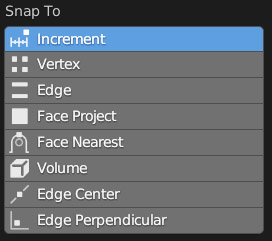
By clicking the magnet-shaped icon ![]() placed in the 3D View header, we will activate the Snap function which is by default of type Increment. After activating the snap, if we try to translate the cube (key G) we will see it move at discrete intervals equal in length to the dimensions of the smallest segment of the grid. This way you will have the possibility, if necessary, to perform transformations constrained to discrete variations with the desired precision. By default, this function applies only to translations, but we can extend it to Scale and Rotate transformations from the snapping menu (icon next to the magnet).
placed in the 3D View header, we will activate the Snap function which is by default of type Increment. After activating the snap, if we try to translate the cube (key G) we will see it move at discrete intervals equal in length to the dimensions of the smallest segment of the grid. This way you will have the possibility, if necessary, to perform transformations constrained to discrete variations with the desired precision. By default, this function applies only to translations, but we can extend it to Scale and Rotate transformations from the snapping menu (icon next to the magnet).
In that case, rotations are made discrete and equal to multiples of 5°.
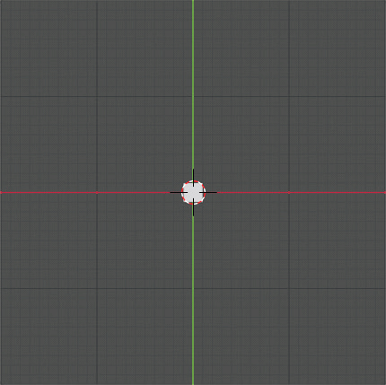
Snap is also useful for positioning the cursor exactly above a vertex of the grid. Let’s suppose that the cursor is positioned inside a square of the grid, regardless of the zoom level of the top/front/right view.
By pressing the F3 key, we will start the Search Menu, which allows for quick searches among the many options of Blender.
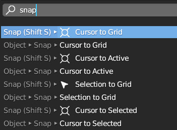
By typing Snap, we immediately see that many options concern the cursor (these options are also found in the Object Context Menu that appears by right-clicking inside the 3D View). With Snap Cursor to Grid, the cursor goes to exactly above the nearest grid vertex. The increment snap can be used in edit mode (next paragraph) for precise transformations on vertices, edges, and faces of a 3D model. Situations where the remaining snapping options might also be useful.
Any object in the scene can be deleted (key X) or duplicated (Shift-D). When duplicating an object, it will initially be in the exact same position as the original with the Move transformation automatically active (we will see that this also applies to vertices or faces of the model). There is a special duplication (Alt-D) that will keep the object connected to its duplicates, so that they can all be modified in the same way by acting on only one of them (creating an instance), but this will only apply to changes made in edit mode (par. 1.5). Now that we are able to perform the first significant transformations on the elements of the scene, it becomes essential to know all the functions of Undo:
- Undo: Ctrl-Z
- Restore: Shift-Ctrl-Z
- Undo History:
(Blender Edit menu)
Next paragraph
Previous paragraph
Back to Index
Wishing you an enjoyable and productive study with Blender, I would like to remind you that you can support this project in two ways: by making a small donation through PayPal or by purchasing the professionally formatted and optimized for tablet viewing PDF version on Lulu.com